 SB600
- CP1 SD card interface (SMD version)
SB600
- CP1 SD card interface (SMD version)  (user friendly)
SB600
- CP1 SD card interface (SMD version) (user friendly)
|
|
SB600/C1P/UK101 adding SD card option BOM
INTERFACE
SD CARD INTERFACE (OPTIONAL USB-RS232 TTL ADAPTER):
To
connect the SD card module with the above SD card interface,
it can be directly soldred to the module, or a 16pin IDC ribbon
cable is used.
ACIA SOFTWARE:
The extended ACIA Control register For OSI computers, after ACIA Reset and a time of 2 sec, OSI autoboot (M/L) is active (software reset). Bootloader code BOOT.SYS will be loaded from SD-card when pressing "L". Otherwise nothing will happen.
The extended ACIA Control register is adressed by the control bits CR5,CR6 = 11 followed by a conventional Data out command. Extended commands are grouped into 16 basic sections (upper 4 bits). Within each sections 16 sub functions can be selected (lower 4 bits). In total, 256 extended ACIA control functions are possible. Extended section (high nibble) - Extended sub function number (low nibble)
If auto-pre-set is enabled, EEPROM specified parameters (Baudrate, bits,RTS,CTS ) will be used to initialize the ACIA on power up.
Hardware serial output/Input of data is not active during special function mode ! Note: If operation was successful,
in some funtions 0x01
is returned, on Error a value of zero is returned. 7: Set FIFO to 4 , no return (RTS/CTS handshake by user) 7: Set FIFO to 8 , no return (RTS/CTS handshake by user) 8: Set FIFO to 16 , no return (provides automatic RTS/CTS handshake) 9: read 1 byte from EEPROM, startL, startH, return 1 bytes (0 to 1023) 10:
write 1 bytes from EEPROM, startL, startH, byte, return 1 byte (control), start at
16 Section 1 Execute Loader Code in binary with leading start address, no return value (just expreimental) 0: PreLoader (0240) to load BOOT.SYS from SD Section 2 Select baud rate, no return value (SW=software defined, HW=by OSI typical TX clocks) Note: HW are the only baud rates supported by emulation and TX clock analysis at startup TX
clock cannot be used directly for the emulated UART due to hardware
restrictions ! 1: 150 only SW 2: 300 +HW 3: 600 +HW 4: 1200 +HW 5: 2400 +HW 6: 4800 +HW 7: 9600 +HW 8: 14400 only SW 9: 19200 +HW 10: 38400 +HW 11: 57600 only SW -> transmit works, rest not reliable 12: 76800 only SW -> non standard, not tested 13: 115200 only SW -> transmit works, rest not reliable 14: 125000 only SW -> not tested 15:
31250 only SW ->> MIDI IN/OUT, +1.58% faster compared to MIDI 0:
start and check SD card, returns 1 if available, 0 if not (will cause WDT
Reset) 12: delete file or folder, return 1 byte 13: rename file, new filename, name ends with byte zero (max 24 characters), return 1 byteNote: before rename, do step 3,5 and 4, to define file to be renamed ! 14:write file, 2 bytes file size, return 1 byte 0/1 , if file allocation complete. followed by binary data, terminated by write to control port, return 1 byte 0/1 when done 15:Get last SD Error, return 1 byte Section 4 IRQ enable/disable timer, does not set IRQ flag in Status register Note: can be active even in IRQ enable is not set, IRQ resets after 10µsec by itself 0: disable timer IRQ 1: IRQ on CTS goes low. IRQ resets after 14µsec by itself Note: CTS can be used as an interrupt
input and disables normal CTS behavior 15:
reset OSCCAL to calibration value
-Using PD5 (RTS) output as fast PWM (8bit
31khz)
-Using Debug port for Serial IN/OUT and selection by RTS with 1 byte in 2 usec -Using Debug port for SPI RAM/FLASH memory, selection by RTS
SOFTWARE FOR OPERATION CONFIG.PRG: BOOT.SYS: There
are different versions of BOOT.SYS for different memory configurations
like 4k, 8k, 16k, 24k 32k and 40k systems. The reason is, BOOT.SYS
places itself at the TOP of memory and leaves the BASIC memory
untouched. Note: to use BOOT.SYS on OSI sytems, a cold-start has to be done to initialize ROM BASIC. Recognized file extensions: .PRG - This are binary programs with two leading bytes representing the start address (like Commodore software) .BAS - This is the standard BASIC text file from Cassette, like it is generated during a listing .LOD - This is the standard MACHINE CODE text file from Cassette or other machine code programs .HEX and .65V - same as LOD In
addition, BASIC programs can come in form of a .PRG file. These
Basic files have a special header to allow the BASIC program
to be stored in Binary format. It speeds up program loading
by more than a factor of 10. To store BASIC programs in .PRG
format, you can use my Emulator and save your program under
Load/Save Binary in the file menu. BASIC_PLUS.PRG: New BASIC commands: -
SDLIST (prints current folder content) Note: Running the standard BOOT.SYS program will end the new BASIC commands to be recognized in BASIC. HARDWARE AVAILABILITY If
you are interested in the SD card module, I could provide the
PCB and the programmed PLD plus microcontroller either in the
SMD or DIP version. All other standard components or connectors,
sockets , SD card interface or USB to RS232 TTL and so
on are not included. So
you need to have sufficient soldering skills and need to buy some some
of the additional components to finally assemble the boards.
PLD and contoller firmware source are not part of the SD card interface.
|
|
Schematics |
|
![]()
Last Update: May 2025
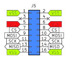 SD card inteface
 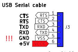 RS232 TTL / USB interface
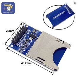 full size SD card interface
 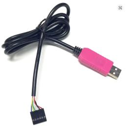 6-Pin PL2303HXD