The purpose of this experiment is to observe ionic and covalent substances both macroscopically and microscopically and to use Lewis structures to predict shape and polarity of molecules.
There are multiple ways of representing the substances that are used in lab. We can look at substances on the macroscopic level (visible to the naked eye) to observe its physical properties. However, we are also interested in understanding what is occurring at the level we cannot see; the microscopic level. What atoms and how many of each are present in a compound? How are the atoms connected? Furthermore, it is helpful to represent these substances with a symbolic representation known as a chemical formula. Examples of these representations are shown in Figure MGP.1
The particulate or microscopic view depends on whether the substance is ionic or covalent. Ionic compounds are described as ratios called formula units. These ratios indicate the simplest (smallest) ratio of positive and negative ions present in the compound. Covalent (or molecular) compounds consist of atoms bound together into individual units called molecules. In Figure MGP.1, the structure of a single molecule of sucrose (\( \ce {C12H22O11} \)) and the structure of a salt cube composed of many formula units of sodium chloride (NaCl) are shown.
Chemists have several ways of representing compounds and molecules symbolically. The simplest form is the chemical formula. If the compound is ionic, there is only one way to write the chemical formula because the ionic formula is the smallest ratio of cations to anions, such as NaCl or \( \ce {MgCl2} \). For covalent (molecular) substances, a formula that shows how many atoms are bonded together in the molecule is called the molecular formula. Consider the formula \( \ce {C2H4O2} \). The even-numbered subscripts indicate this is not the simplest ratio of atoms. This because a molecule of this compound contains 2 carbon atoms, 4 hydrogen atoms, and 2 oxygen covalently bonded together. A molecule with the formula \( \ce {CH2O} \) would be a different compound.
The limitation of a chemical formula in covalent compounds is that it does not show how the atoms are connected to one another. This information is available in a structural formula. Two possible structures for \( \ce {C2H4O2} \) are shown in Figure MGP.2.
The structures in Figure MGP.2 have the same number of C’s, H’s and O’s, but are bonded together differently. These structures represent two distinct compounds with different physical and chemical properties. These structural formulas tell a chemist much more information about the covalent compound than the molecular formulas do.
Lewis structures are structural formulas that show how atoms in a molecule share their valence electrons to form covalent bonds. Lewis proposed that electrons are distributed in molecules according to the octet rule, which states that all atoms seek 8 valence electrons like that of a noble gas (with the exception of helium, which only has 2 valence electrons). In a molecule, atoms share electrons in bonds to become more stable. This can be accomplished by filling their valence (or outer) shell with 8 electrons (or 2 in the case of helium). Hydrogen is an exception to the octet rule because it only needs two electrons (a duet) to become stable like the noble gas it is nearest to on the periodic table (helium).
Lewis structures are very good at showing how electrons are distributed in bonds and lone pairs in the molecule. To learn or review how to draw Lewis structures, please refer to the “Writing Lewis Structures” video found on Labflow. While Lewis structures do not directly show the three-dimensional shape of a molecule, the information in a Lewis structure can be used to determine the 3-D shape using VSEPR theory
Valence Shell Electron Pair Repulsion (VSEPR) theory uses Lewis structures to predict and explain the shapes of different molecules. This theory postulates that electrons occupy regions of space in a molecule in a way that allows them to minimize electron-to-electron repulsion. That is, the atoms in a molecule adopt shapes that keep their electron clouds as far away from each other as possible. These shapes are determined by the number of atoms that are directly bonded to the central atom plus the number of lone pairs of electrons on the central atom.
VSEPR starts with drawing the Lewis structure of the molecule of interest, and that Lewis structure is used to predict the shape of the molecule.
| Number of Bonds | Number of Lone Pairs | Total Number of Charge Clouds | Molecular Geometry | Example |
|---|---|---|---|---|
| 2 | 0 | 2 | Linear  |
\(\ce{O=C=O}\) |
| 3 | 0 | 3 | Trigonal planar  |
\(\ce{H2C=O}\) |
| 2 | 1 | 3 | Bent  |
\(\ce{O=S=O}\) |
| 4 | 0 | 4 | Tetrahedral  |
\(\ce{CH4}\) |
| 3 | 1 | 4 | Trigonal pyramidal  |
\(\ce{NH3}\) |
| 2 | 2 | 4 | Bent |
\(\ce{H2O}\) |
The molecular geometry is determined by the total number of separate electron groups (single bonds, double bonds, triple bonds, and lone pairs of electrons) associated with the central atom. Refer to Table MGP.1. The different electron groups occupy positions that maximize the bond angles and thus minimize the repulsion between these negatively charged electron groups. Methane, \( \ce {CH4} \), in Table MGP.1, has 4 separate electron groups (or “charge clouds”) around the central carbon atom. All of these groups are bonds. According to Table MGP.1, a molecule that has 4 bonds and no lone pairs has a tetrahedral molecular geometry. However, in phosphorus trifluoride (\( \ce {PF3} \), Figure MGP.4), the phosphorus central atom has one lone pair and three single bonds. Thus, the molecular geometry is trigonal pyramidal (sometimes simply referred to as pyramidal). The molecular geometry describes the shape due to the atoms in the molecule. However, we cannot ignore the existence of any lone pairs of electrons on the central atom because they also cause repulsion that will impact the orientation of the outer atoms (and thus the molecular shape).
An appreciation of molecular shape is important because much of a molecule’s properties depends on its geometry.
For example, DNA has a specific 3-D structure that is recognized by proteins in order for DNA to be replicated (which is necessary for cells to multiply). The chemotherapeutic drug, cisplatin, helps combat cancer by binding to DNA and altering its 3-D structure. The proteins that normally recognize DNA based on its shape are unable to bind to the DNA and the cancer cells can no longer multiply. The shapes of large molecules, such as DNA or proteins, is determined the same way as smaller molecules. Therefore, the principles you’ll learn here apply to more complex systems beyond the scope of this course.
Consider a tetrahedral molecule where the central atom is bonded to four other atoms, such as methane, \( \ce {CH4} \), as shown in Figure MGP.3. If a bond is in the plane of the paper, it is drawn with a simple line:

If a bond is coming out toward you, it is drawn with a solid wedge, and its angle is often chosen to provide some “perspective.”

If a bond is going away from you, it is drawn with a dashed wedge, and its angle is often chosen to provide some “perspective.”

Thus, a tetrahedral \( \ce {CH4} \) molecule would be drawn as shown in Figure MGP.3a with the carbon and two hydrogen atoms connected by solid bonds. These bonds are in the plane of the paper. The bond to one hydrogen atom projects down and in front of the paper while the bond to the fourth hydrogen atom projects down and behind the paper. Figure MGP.3b is a ball-and-stick model of methane similar to the one you will see in the simulation. Keep in mind that molecules rotate and the 3-D representation shown below is just one example for methane.
Polarity occurs when electric charge is not evenly distributed, which leads to poles (positive and negative). Ionic compounds, by their nature, are polar because one particle is positively charged and the other is negatively charged. Molecules, on the other hand, can be polar or nonpolar. A polar molecule has a distinct region that has a slight negative charge and another distinct region that is slightly positive. A nonpolar molecule has an even distribution of charge. Many of the physical and chemical properties of compounds are determined by their polarity. For example, polar compounds are far more likely to dissolve in polar solvents such as water than in nonpolar solvents such as oil.
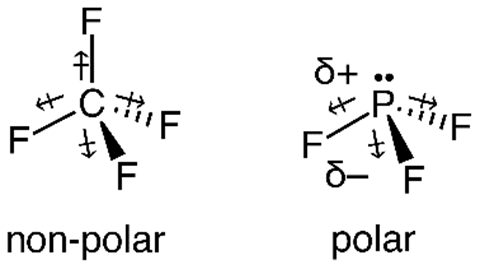
Polar molecules arise when the molecule is asymmetric. Consider the compounds carbon tetrafluoride, \( \ce {CF4} \), and phosphorus trifluoride, \( \ce {PF3} \). Figure MGP.4 shows three different types of 3D models, all of which show the overall shapes of these molecules, derived from their Lewis structures (models a and e). Models c and g represent a ball-and-stick model that looks very much like the types of models you will build during this lab activity. The dash-wedge model (b and f) allows you to draw the model on paper showing its three dimensions. However, when models represent bonds as lines/wedges or sticks, the space between the atoms is greatly exaggerated. The final model, the space- filling model (d and h), is a more accurate view of the actual molecule. However, it can be difficult to see the shapes clearly in space-filling models, which is why you will build ball-and-stick models and draw structures showing bonds as lines and wedges.
The \( \ce {CF4} \) molecule is tetrahedral and symmetrical, with all four points of the tetrahedron occupied by fluorine atoms. The \( \ce {PF3} \) molecule has three bonds with one lone pair, giving it a trigonal pyramidal molecular geometry. The \( \ce {PF3} \) molecule is a pyramid with three fluorine atoms at the base and a phosphorus atom at the top. Thus, the \( \ce {PF3} \) molecule is asymmetrical.
Electronegativity is the relative pull, or attraction, of electrons in a covalent bond. Electronegativity increases from lower left on the periodic table to the upper right of the periodic table. Due to this periodic trend, we see that fluorine has a higher electronegativity value compared to carbon or phosphorus because it is further to the upper right on the periodic table. This means fluorine attracts the electrons in the covalent bond more strongly than C or P, making C–F and P–F bonds very polar. In Figure MGP.5, each of the individual polar bonds is labeled with a dipole arrow pointing toward the atom of greater electronegativity (toward fluorine).
In a molecule with multiple polar bonds, the bond dipoles combine to form an overall dipole for the molecule. Because \( \ce {CF4} \) is a symmetric molecule, the dipole arrows cancel one another resulting in a nonpolar molecule. Although it contains 4 highly polar C-F bonds, \( \ce {CF4} \) is nonpolar because it is a symmetrical molecule.
In asymmetric molecules, the dipole arrows do not cancel. Thus, asymmetric \( \ce {PF3} \) is a polar molecule. We denote the areas of negative and positive charge with \(\updelta \) symbols (delta) – indicating slightly or partially negative (\({\updelta }^{-}\)) and slightly or partially positive (\({\updelta }^{+}\))areas of the molecule. \( \ce {PF3} \) contains 3 highly polar P-F bonds, and, because it is asymmetrical, \( \ce {PF3} \) is a polar compound.
Another way to show polarity in a molecule is to use an electrostatic potential map of the molecule. In these maps, red represents areas of increased negative charge (electron-rich areas) and blue indicates electron-poor regions. Electrostatic potential maps of \( \ce {CF4} \) and \( \ce {PF3} \) are in Figure MGP.6.
When making solutions by mixing a solute with a solvent, polarity plays an important role in how well the solute dissolves in the solvent. A helpful phrase often used to predict solubility of a substance within another substance is “like dissolves well in like”. This means a polar solute will dissolve well in a polar solvent, but not in a nonpolar solvent. Furthermore, a nonpolar solute will dissolve well in a nonpolar solvent, but not in a polar solvent.
1.
Examine the macroscopic images of the chemical samples. They are sodium
chloride (table salt), and three covalent substances: table sugar (sucrose), iodine
crystals, and powdered sulfur. Record two or three physical properties you
observed about each substance in your lab notebook.
2.
Observe the microscopic view of a NaCl crystal model on the computer screen.
NaCl will be your only example shown for both a micro and macro view. Record
a description of this view in your lab notebook
1.
View the demonstration for polarity of various substances. Note that each vial
has two liquid layers, water and oil. Record observations regarding any
interaction between the substances and the liquids in each layer. Also
note that the appearance of the substance (iodine, copper sulfate, etc.)
before it is added to the liquid is listed underneath the substance in
parenthesis.
2.
Classify each of the compounds on display as a polar or nonpolar.
1.
In your notebook, draw Lewis structures for the Group 1 compounds found in
Report Table MGP.3. Start by determining and recording the number of
valence electrons. Determine the number of lone pairs of electrons as
well.
2.
Go to this website: https://phet.colorado.edu/sims/html/molecule-shapes/latest/molecule-shapes˙en.html
and build each of these molecules.
3.
Complete the columns in Report Table MGP.4.
4.
Repeat steps 1-3 with the Group 2 compounds and then complete Report
Table MGP.5.
Name:
Section: ________________ Date: ______________________
Describe the atomic (microscopic) perspective of a sodium chloride crystal as shown in the computer modeling software.
Based on the observations you recorded in Report Table MGP.2, classify each of
the compounds as one of the following: polar or nonpolar.
Sodium chloride:
Sulfur:
Iodine:
Copper(II) sulfate:
| Methane, \( \ce {CH4} \) | Ammonia, \( \ce {NH3} \) |
| Valence e\(^{-}\) = | Valence e\(^{-}\) = |
| Number of lone pairs of electrons = | Number of lone pairs of electrons = |
|
| |
|
|
|
| Water, \( \ce {H2O} \) | Carbonate, \( \ce {CO3^{2-}} \) |
| Valence e\(^{-}\) = | Valence e\(^{-}\) = |
| Number of lone pairs of electrons = | Number of lone pairs of electrons = |
|
|
|
|
|
|
|
|
|
|
|
|
| Sulfur dioxide, \( \ce {SO2} \) | Carbon dioxide, \( \ce {CO2} \) |
| Valence e\(^{-}\) = | Valence e\(^{-}\) = |
| Number of lone pairs of electrons = | Number of lone pairs of electrons = |
|
|
|
|
|
|
|
|
|
|
|
|
|
|
| Molecular Formula | \( \ce{CH4}\) | \( \ce{NH3}\) | \( \ce{H2O}\) | \( \ce{CO3^{2-}}\) | \( \ce{SO2}\) | \( \ce{CO2}\) |
|---|---|---|---|---|---|---|
| # Atoms Directly Bonded to Central Atom | ||||||
| # Lone Pairs on Central Atom | ||||||
| Molecular Geometry | ||||||
| # Bonds with Dipole | ||||||
| Do Dipoles Cancel? Y/N/NA | ||||||
| Is Molecule Polar? Y/N |
| Nitrogen, \( \ce {N2} \) | Hydrogen cyanide, HCN (C is central atom) |
| Valence e\(^{-}\) = | Valence e\(^{-}\) = |
| Number of lone pairs of electrons = | Number of lone pairs of electrons = |
|
| |
|
| |
| Hydronium ion, \( \ce {H3O+} \) | Iodine, \( \ce {I2} \) |
| Valence e\(^{-}\) = | Valence e\(^{-}\) = |
| Number of lone pairs of electrons = | Number of lone pairs of electrons = |
|
|
|
|
|
|
|
|
|
|
|
|
| Ammonium ion, \( \ce {NH4^+} \) | Formaldehyde, \( \ce {CH2O} \) (C is central atom) |
| Valence e\(^{-}\) = | Valence e\(^{-}\) = |
| Number of lone pairs of electrons = | Number of lone pairs of electrons = |
|
|
|
|
|
|
|
|
|
|
|
|
|
|
| Molecular Formula | \( \ce{N2}\) | \( \ce{HCN}\) | \( \ce{H3O^{+}}\) | \( \ce{I2}\) | \( \ce{NH4^{+}}\) | \( \ce{CH2O}\) |
|---|---|---|---|---|---|---|
| # Atoms Directly Bonded to Central Atom | ||||||
| # Lone Pairs on Central Atom | ||||||
| Molecular Geometry | ||||||
| # Bonds with Dipole | ||||||
| Do Dipoles Cancel? Y/N/NA | ||||||
| Is Molecule Polar? Y/N |
1.
The capsicum molecule is shown below, and one tetrahedral center has
been identified. Use arrows to identify three other centers that have a
different molecular geometry. Label each one with its molecular geometry.
You must choose centers that all have different molecular geometry
from each other, and you may NOT use another tetrahedral center.

2.
Although \( \ce {CO3^{2-}} \) and \( \ce {CH2O} \) have similar shapes,
one is polar and the other is nonpolar. Explain why.
3.
By now you should realize that having an octet of valence electrons on an atom
(with the exception of hydrogen) is critical for a molecule to be stable.
Would you expect NO and \( \ce {NO2} \) to be stable molecules?
Why or Why not? Include Lewis structures as part of your explanation.
 b
b c
c d
d

 b
b 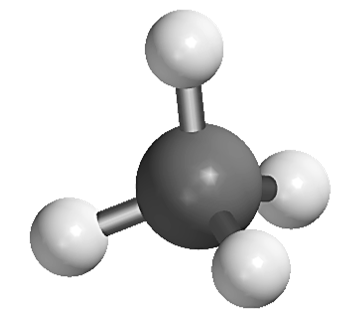
 b
b  c
c  d
d 
 f
f  g
g  h
h 
 b
b 