
Stress analysis software plays a crucial role in predicting the structural integrity of a design by simulating and analyzing the distribution of stress within the structure. It uses advanced algorithms and mathematical models to calculate the stress levels at different points in the design, taking into account factors such as material properties, applied loads, and boundary conditions. By inputting the design parameters and load conditions into the software, engineers can obtain accurate predictions of stress distribution and identify potential areas of concern. This allows them to make informed decisions and modifications to ensure the structural integrity of the design.
Stress analysis software offers several key features that enable engineers to analyze complex load conditions. Firstly, it allows for the simulation of various types of loads, including static, dynamic, and thermal loads. This flexibility enables engineers to assess the design's response to different operating conditions. Additionally, the software provides advanced meshing capabilities, allowing engineers to divide the design into smaller elements for more accurate stress calculations. It also offers visualization tools, such as contour plots and color-coded stress maps, which help engineers interpret and analyze the stress distribution. Furthermore, the software often includes post-processing capabilities, allowing engineers to extract and analyze specific stress values or perform further calculations.
Big Daishowa specializes in modular workholding that provides flexibility, efficiency and functionality. UNILOCK zero-point workholding provides value through versatile solutions that are simple to integrate into existing machinery and setups. Here, the company examines four tips for choosing the right workholding device.
Posted by on 2022-07-28
AddUp, a joint venture created by Michelin and Fives, is a global metal additive manufacturing OEM and service provider of powder bed fusion (PBF) and directed energy deposition (DED) technologies. They have launched a suite of new process monitoring software to bolster the capabilities of the FormUp 350 PBF machine: AddUp Dashboards, Recoat Monitoring, and Meltpool Monitoring. This new software suite for its metal 3D printing technology optimizes part quality for prototyping and end-use industrial applications.
Posted by on 2022-07-06
Nidec Machine Tool Corporation recently developed the "SE25FR Plus," a gear shaping machine dedicated to making high-precision small-module gears used in robots. The company simultaneously developed a small-module cutting tool specifically for the new gear shaping machine. By providing this dual support in high-precision gear cutting machines and cutting tools from a single source, Nidec Machine Tool responds to the need for reduction gears of increasingly higher precision in the expanding global robot market.
Posted by on 2022-06-30
Klingelnberg examines gear noise behavior and the evolution of the electric powertrain.
Posted by on 2022-06-14
In July, Raymond J. Drago, P.E.—chief engineer of Drive Systems Technology, Inc. (DST), a mechanical power transmission consulting organization that he founded in 1976—will lead an IACET-accredited course on both the geometry and rating of involute splines of various types along with their applications. Topics under discussion include spline configuration variations, including half depth, full depth, and special function designs; both fixed and flexible spline configurations in terms of usage and design; lubrication methods, including grease, oil bath, and flowing oil, as well as coatings appropriate for various spline applications; and shear and compressive stress rating methods with analyses methodology in both equation and graphical methodology via various rating charts.
Posted by on 2022-05-29
Stress analysis software assists in identifying potential failure points in a design by highlighting areas of high stress concentration. By analyzing the stress distribution, engineers can identify regions where the stress levels exceed the material's yield or ultimate strength. These areas are prone to failure and require attention. The software can also provide information on the nature of the stress, such as whether it is tensile, compressive, or shear stress. This helps engineers understand the specific failure mechanisms that may occur and take appropriate measures to mitigate them, such as adding reinforcements or modifying the design geometry.
Yes, stress analysis software is capable of simulating different types of loads, including static, dynamic, and thermal loads. Static loads refer to steady or constant loads applied to the structure, while dynamic loads involve varying or time-dependent loads. Thermal loads, on the other hand, consider the effects of temperature changes on the structure. By simulating these different load conditions, engineers can assess the design's response and determine its structural integrity under various operating scenarios. This comprehensive analysis allows for a more accurate assessment of the design's performance and helps identify potential issues that may arise in real-world conditions.
Using stress analysis software offers several advantages over traditional manual calculations for determining stress distribution. Firstly, the software provides a more accurate and precise analysis by considering complex factors such as material properties, load conditions, and boundary conditions. This eliminates the potential for human error and ensures reliable results. Additionally, the software allows for faster analysis and evaluation of multiple design iterations, saving time and resources. It also offers visualization tools that provide a clear and intuitive representation of stress distribution, making it easier for engineers to interpret and analyze the results. Overall, stress analysis software enhances the efficiency and accuracy of the design process, leading to improved structural integrity and reduced risk of failure.
Stress analysis software helps in optimizing the design by suggesting modifications to reduce stress concentrations. By analyzing the stress distribution, the software can identify areas of high stress concentration, which are potential weak points in the design. Based on this information, the software can provide recommendations for design modifications, such as adding reinforcements, changing material properties, or altering the geometry. These suggestions aim to redistribute the stress more evenly throughout the structure, reducing stress concentrations and improving the overall structural integrity. By incorporating these modifications, engineers can optimize the design and ensure its performance meets the desired criteria.
Yes, stress analysis software can provide visual representations of stress distribution, such as contour plots or color-coded stress maps. These visualizations offer a clear and intuitive way to understand the stress distribution within the design. Contour plots display stress levels using contour lines, allowing engineers to visualize the magnitude and distribution of stress. Color-coded stress maps assign different colors to different stress levels, providing a quick and easy way to identify areas of high stress concentration. These visual representations enable engineers to identify potential failure points, assess the effectiveness of design modifications, and communicate the analysis results to stakeholders effectively.
Wear debris analysis for assessing gearbox health involves collecting and examining particles and fragments that have worn off from the gears and other components within the gearbox. This process typically includes using techniques such as ferrography, spectroscopy, and microscopy to identify the composition, size, shape, and quantity of the wear debris. The analysis also involves assessing the distribution and concentration of the debris within the lubricant. By analyzing the wear debris, engineers can gain insights into the type and severity of wear taking place within the gearbox, as well as potential issues such as abrasion, adhesion, or fatigue. This information helps in determining the overall health and condition of the gearbox, allowing for proactive maintenance and minimizing the risk of unexpected failures.
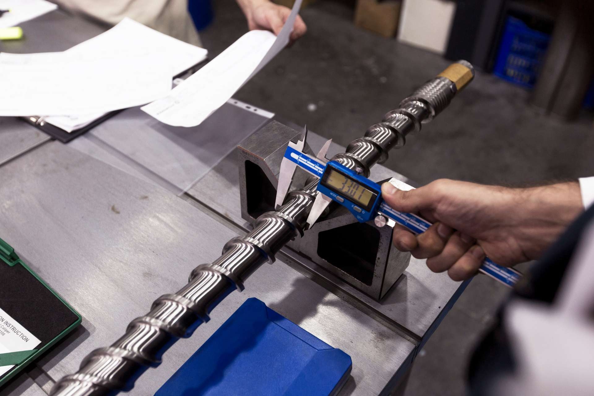
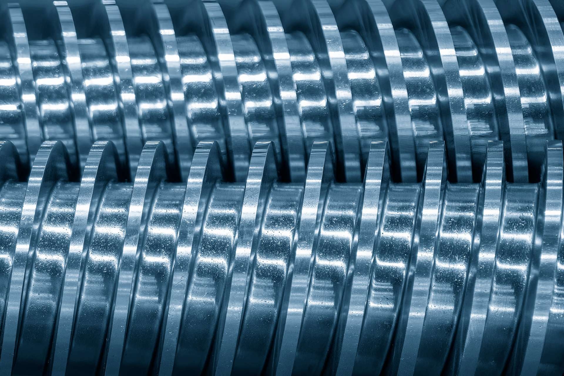
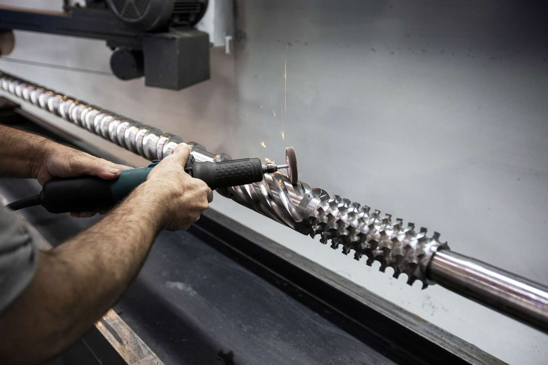
Dimensional verification of screws and barrels involves several procedures to ensure accuracy and precision. One common procedure is the use of precision measuring instruments such as calipers, micrometers, and gauges to measure the key dimensions of the screws and barrels. These instruments allow for the precise measurement of parameters such as diameter, length, pitch, and thread profile. Additionally, optical comparators and coordinate measuring machines (CMMs) may be used to verify the dimensional accuracy of the screws and barrels by comparing them to a reference standard or CAD model. This helps to identify any deviations or variations in the dimensions. Furthermore, the use of statistical process control (SPC) techniques can be employed to monitor and control the dimensional variations during the manufacturing process. This involves collecting data on the dimensions of the screws and barrels at various stages and analyzing them to ensure they fall within the specified tolerances. Overall, these procedures ensure that the screws and barrels meet the required dimensional specifications and maintain the desired quality standards.
Composite materials are commonly integrated into gearbox design to enhance the overall performance and durability of the system. These materials, which are made by combining two or more different types of materials, offer a unique combination of properties that make them ideal for gearbox applications. For instance, carbon fiber composites are often used in the construction of gearbox casings due to their high strength-to-weight ratio and excellent resistance to fatigue and impact. Additionally, the use of composite materials in gear teeth can improve their wear resistance and reduce noise and vibration levels. By incorporating composite materials into gearbox design, engineers can optimize the efficiency, reliability, and lifespan of the system, ultimately leading to improved performance and reduced maintenance costs.
Thermal barrier coatings find various applications in gearboxes, enhancing their performance and durability. These coatings act as a protective layer, reducing heat transfer and minimizing thermal stresses within the gearbox components. By mitigating heat generation and dissipation, thermal barrier coatings help prevent premature wear, corrosion, and fatigue in gears, bearings, and other critical parts. Additionally, these coatings improve the overall efficiency of the gearbox by reducing friction and minimizing energy losses. The use of thermal barrier coatings in gearboxes also allows for higher operating temperatures, enabling the transmission of higher torque and power. Overall, the application of thermal barrier coatings in gearboxes significantly improves their reliability, longevity, and performance in demanding industrial and automotive environments.
Surface roughness on gearbox components is typically measured using specialized equipment such as a profilometer or a surface roughness tester. These instruments utilize various techniques to assess the texture and irregularities on the surface of the components. One common method is the stylus-based technique, where a stylus is moved across the surface, and its vertical displacement is measured. This data is then used to calculate parameters such as Ra (average roughness) and Rz (mean peak-to-valley height). Another technique is the optical method, which employs light interference patterns to determine the surface roughness. Additionally, advanced technologies like laser scanning and 3D imaging are also employed to provide a comprehensive analysis of the surface topography. These measurements are crucial in ensuring the quality and performance of gearbox components, as they directly impact factors such as friction, wear, and noise levels.
Condition monitoring in gearbox systems typically utilizes a variety of sensors to detect and analyze different parameters. These sensors may include vibration sensors, temperature sensors, oil analysis sensors, acoustic emission sensors, and magnetic field sensors. Vibration sensors are used to measure the vibration levels within the gearbox, while temperature sensors monitor the temperature of the gearbox components. Oil analysis sensors are employed to assess the condition of the lubricating oil, while acoustic emission sensors detect any abnormal sounds or vibrations. Magnetic field sensors can also be used to monitor gear tooth wear and detect any metal particles in the oil. By utilizing these various sensors, condition monitoring systems can provide comprehensive data on the health and performance of gearbox systems.