|
|
The accessibility of this article is in question. The specific issue is: animation fails MOS, see talk. Relevant discussion may be found on the talk page. (April 2025)
|
Device that imparts energy to the fluids by mechanical action
"Water Pump" redirects here. For the community in Pakistan, see Water Pump, Karachi.
For other uses of "pump" or "pumps", see Pump (disambiguation).
 A small, electrically powered pump
 A large, electrically driven pump for waterworks near the Hengsteysee, Germany
A pump is a device that moves fluids (liquids or gases), or sometimes slurries,[1] by mechanical action, typically converted from electrical energy into hydraulic or pneumatic energy.
Mechanical pumps serve in a wide range of applications such as pumping water from wells, aquarium filtering, pond filtering and aeration, in the car industry for water-cooling and fuel injection, in the energy industry for pumping oil and natural gas or for operating cooling towers and other components of heating, ventilation and air conditioning systems. In the medical industry, pumps are used for biochemical processes in developing and manufacturing medicine, and as artificial replacements for body parts, in particular the artificial heart and penile prosthesis.
When a pump contains two or more pump mechanisms with fluid being directed to flow through them in series, it is called a multi-stage pump. Terms such as two-stage or double-stage may be used to specifically describe the number of stages. A pump that does not fit this description is simply a single-stage pump in contrast.
In biology, many different types of chemical and biomechanical pumps have evolved; biomimicry is sometimes used in developing new types of mechanical pumps.
Types
[edit]
Mechanical pumps may be submerged in the fluid they are pumping or be placed external to the fluid.
Pumps can be classified by their method of displacement into electromagnetic pumps, positive-displacement pumps, impulse pumps, velocity pumps, gravity pumps, steam pumps and valveless pumps. There are three basic types of pumps: positive-displacement, centrifugal and axial-flow pumps. In centrifugal pumps the direction of flow of the fluid changes by ninety degrees as it flows over an impeller, while in axial flow pumps the direction of flow is unchanged.[2][3]
See also: Vacuum pump
Electromagnetic pump
[edit]
This section is an excerpt from Electromagnetic pump.[edit]
An electromagnetic pump is a pump that moves liquid metal, molten salt, brine, or other electrically conductive liquid using electromagnetism.
A magnetic field is set at right angles to the direction the liquid moves in, and a current is passed through it. This causes an electromagnetic force that moves the liquid.
Applications include pumping molten solder in many wave soldering machines, pumping liquid-metal coolant, and magnetohydrodynamic drive.
Positive-displacement pumps
[edit]
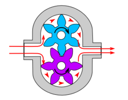
 Lobe pump internals
 Lobe pump internals
A positive-displacement pump makes a fluid move by trapping a fixed amount and forcing (displacing) that trapped volume into the discharge pipe.
Some positive-displacement pumps use an expanding cavity on the suction side and a decreasing cavity on the discharge side. Liquid flows into the pump as the cavity on the suction side expands and the liquid flows out of the discharge as the cavity collapses. The volume is constant through each cycle of operation.
Positive-displacement pump behavior and safety
[edit]
Positive-displacement pumps, unlike centrifugal, can theoretically produce the same flow at a given rotational speed no matter what the discharge pressure. Thus, positive-displacement pumps are constant flow machines. However, a slight increase in internal leakage as the pressure increases prevents a truly constant flow rate.
A positive-displacement pump must not operate against a closed valve on the discharge side of the pump, because it has no shutoff head like centrifugal pumps. A positive-displacement pump operating against a closed discharge valve continues to produce flow and the pressure in the discharge line increases until the line bursts, the pump is severely damaged, or both.
A relief or safety valve on the discharge side of the positive-displacement pump is therefore necessary. The relief valve can be internal or external. The pump manufacturer normally has the option to supply internal relief or safety valves. The internal valve is usually used only as a safety precaution. An external relief valve in the discharge line, with a return line back to the suction line or supply tank, provides increased safety.
Positive-displacement types
[edit]
A positive-displacement pump can be further classified according to the mechanism used to move the fluid:
- Rotary-type positive displacement: internal and external gear pump, screw pump, lobe pump, shuttle block, flexible vane and sliding vane, circumferential piston, flexible impeller, helical twisted roots (e.g. the Wendelkolben pump) and liquid-ring pumps
- Reciprocating-type positive displacement: piston pumps, plunger pumps and diaphragm pumps
- Linear-type positive displacement: rope pumps and chain pumps
Rotary positive-displacement pumps
[edit]
 Rotary vane pump
These pumps move fluid using a rotating mechanism that creates a vacuum that captures and draws in the liquid.[4]
Advantages: Rotary pumps are very efficient[5] because they can handle highly viscous fluids with higher flow rates as viscosity increases.[6]
Drawbacks: The nature of the pump requires very close clearances between the rotating pump and the outer edge, making it rotate at a slow, steady speed. If rotary pumps are operated at high speeds, the fluids cause erosion, which eventually causes enlarged clearances that liquid can pass through, which reduces efficiency.
Rotary positive-displacement pumps fall into five main types:
- Gear pumps – a simple type of rotary pump where the liquid is pushed around a pair of gears.
- Screw pumps – the shape of the internals of this pump is usually two screws turning against each other to pump the liquid
- Rotary vane pumps
- Hollow disc pumps (also known as eccentric disc pumps or hollow rotary disc pumps), similar to scroll compressors, these have an eccentric cylindrical rotor encased in a circular housing. As the rotor orbits, it traps fluid between the rotor and the casing, drawing the fluid through the pump. It is used for highly viscous fluids like petroleum-derived products, and it can also support high pressures of up to 290 psi.[7][8][9][10][11][12][13]
- Peristaltic pumps have rollers which pinch a section of flexible tubing, forcing the liquid ahead as the rollers advance. Because they are very easy to keep clean, these are popular for dispensing food, medicine, and concrete.
Reciprocating positive-displacement pumps
[edit]
 Simple hand pump
 Antique "pitcher" pump (c. 1924) at the Colored School in Alapaha, Georgia, US
See also: Reciprocating pump
Reciprocating pumps move the fluid using one or more oscillating pistons, plungers, or membranes (diaphragms), while valves restrict fluid motion to the desired direction. In order for suction to take place, the pump must first pull the plunger in an outward motion to decrease pressure in the chamber. Once the plunger pushes back, it will increase the chamber pressure and the inward pressure of the plunger will then open the discharge valve and release the fluid into the delivery pipe at constant flow rate and increased pressure.
Pumps in this category range from simplex, with one cylinder, to in some cases quad (four) cylinders, or more. Many reciprocating-type pumps are duplex (two) or triplex (three) cylinder. They can be either single-acting with suction during one direction of piston motion and discharge on the other, or double-acting with suction and discharge in both directions. The pumps can be powered manually, by air or steam, or by a belt driven by an engine. This type of pump was used extensively in the 19th century—in the early days of steam propulsion—as boiler feed water pumps. Now reciprocating pumps typically pump highly viscous fluids like concrete and heavy oils, and serve in special applications that demand low flow rates against high resistance. Reciprocating hand pumps were widely used to pump water from wells. Common bicycle pumps and foot pumps for inflation use reciprocating action.
These positive-displacement pumps have an expanding cavity on the suction side and a decreasing cavity on the discharge side. Liquid flows into the pumps as the cavity on the suction side expands and the liquid flows out of the discharge as the cavity collapses. The volume is constant given each cycle of operation and the pump's volumetric efficiency can be achieved through routine maintenance and inspection of its valves.[14]
Typical reciprocating pumps are:
- Plunger pump – a reciprocating plunger pushes the fluid through one or two open valves, closed by suction on the way back.
- Diaphragm pump – similar to plunger pumps, where the plunger pressurizes hydraulic oil which is used to flex a diaphragm in the pumping cylinder. Diaphragm valves are used to pump hazardous and toxic fluids.
- Piston pump displacement pumps – usually simple devices for pumping small amounts of liquid or gel manually. The common hand soap dispenser is such a pump.
- Radial piston pump – a form of hydraulic pump where pistons extend in a radial direction.
- Vibratory pump or vibration pump – a particularly low-cost form of plunger pump, popular in low-cost espresso machines.[15][16] The only moving part is a spring-loaded piston, the armature of a solenoid. Driven by half-wave rectified alternating current, the piston is forced forward while energized, and is retracted by the spring during the other half cycle. Due to their inefficiency, vibratory pumps typically cannot be operated for more than one minute without overheating, so are limited to intermittent duty.
Various positive-displacement pumps
[edit]
The positive-displacement principle applies in these pumps:
- Rotary lobe pump
- Progressing cavity pump
- Rotary gear pump
- Piston pump
- Diaphragm pump
- Screw pump
- Gear pump
- Hydraulic pump
- Rotary vane pump
- Peristaltic pump
- Rope pump
- Flexible impeller pump
Gear pump
[edit]
 Gear pump
Main article: Gear pump
This is the simplest form of rotary positive-displacement pumps. It consists of two meshed gears that rotate in a closely fitted casing. The tooth spaces trap fluid and force it around the outer periphery. The fluid does not travel back on the meshed part, because the teeth mesh closely in the center. Gear pumps see wide use in car engine oil pumps and in various hydraulic power packs.
Screw pump
[edit]
 Screw pump
Main article: Screw pump
A screw pump is a more complicated type of rotary pump that uses two or three screws with opposing thread — e.g., one screw turns clockwise and the other counterclockwise. The screws are mounted on parallel shafts that often have gears that mesh so the shafts turn together and everything stays in place. In some cases the driven screw drives the secondary screw, without gears, often using the fluid to limit abrasion. The screws turn on the shafts and drive fluid through the pump. As with other forms of rotary pumps, the clearance between moving parts and the pump's casing is minimal.
Progressing cavity pump
[edit]
Main article: Progressing cavity pump
 Progressing cavity pump
Widely used for pumping difficult materials, such as sewage sludge contaminated with large particles, a progressing cavity pump consists of a helical rotor, about ten times as long as its width, and a stator, mainly made out of rubber. This can be visualized as a central core of diameter x with, typically, a curved spiral wound around of thickness half x, though in reality it is manufactured in a single lobe. This shaft fits inside a heavy-duty rubber sleeve or stator, of wall thickness also typically x. As the shaft rotates inside the stator, the rotor gradually forces fluid up the rubber cavity. Such pumps can develop very high pressure at low volumes at a rate of 90 PSI per stage on water for standard configurations.
Roots-type pump
[edit]
 A Roots lobe pump
Main article: Roots-type supercharger
Named after the Roots brothers who invented it, this lobe pump displaces the fluid trapped between two long helical rotors, each fitted into the other when perpendicular at 90°, rotating inside a triangular shaped sealing line configuration, both at the point of suction and at the point of discharge. This design produces a continuous flow with equal volume and no vortex. It can work at low pulsation rates, and offers gentle performance that some applications require.
Applications include:
- High capacity industrial air compressors.
- Roots superchargers on internal combustion engines.
- A brand of civil defense siren, the Federal Signal Corporation's Thunderbolt.
Peristaltic pump
[edit]
 360° peristaltic pump
Main article: Peristaltic pump
A peristaltic pump is a type of positive-displacement pump. It contains fluid within a flexible tube fitted inside a circular pump casing (though linear peristaltic pumps have been made). A number of rollers, shoes, or wipers attached to a rotor compress the flexible tube. As the rotor turns, the part of the tube under compression closes (or occludes), forcing the fluid through the tube. Additionally, when the tube opens to its natural state after the passing of the cam it draws (restitution) fluid into the pump. This process is called peristalsis and is used in many biological systems such as the gastrointestinal tract.
Plunger pumps
[edit]
Main article: Plunger pump
Plunger pumps are reciprocating positive-displacement pumps.
These consist of a cylinder with a reciprocating plunger. The suction and discharge valves are mounted in the head of the cylinder. In the suction stroke, the plunger retracts and the suction valves open causing suction of fluid into the cylinder. In the forward stroke, the plunger pushes the liquid out of the discharge valve. Efficiency and common problems: With only one cylinder in plunger pumps, the fluid flow varies between maximum flow when the plunger moves through the middle positions, and zero flow when the plunger is at the end positions. A lot of energy is wasted when the fluid is accelerated in the piping system. Vibration and water hammer may be a serious problem. In general, the problems are compensated for by using two or more cylinders not working in phase with each other. Centrifugal pumps are also susceptible to water hammer. Surge analysis, a specialized study, helps evaluate this risk in such systems.
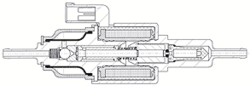
Triplex-style plunger pump
[edit]
Triplex plunger pumps use three plungers, which reduces the pulsation relative to single reciprocating plunger pumps. Adding a pulsation dampener on the pump outlet can further smooth the pump ripple, or ripple graph of a pump transducer. The dynamic relationship of the high-pressure fluid and plunger generally requires high-quality plunger seals. Plunger pumps with a larger number of plungers have the benefit of increased flow, or smoother flow without a pulsation damper. The increase in moving parts and crankshaft load is one drawback.
Car washes often use these triplex-style plunger pumps (perhaps without pulsation dampers). In 1968, William Bruggeman reduced the size of the triplex pump and increased the lifespan so that car washes could use equipment with smaller footprints. Durable high-pressure seals, low-pressure seals and oil seals, hardened crankshafts, hardened connecting rods, thick ceramic plungers and heavier duty ball and roller bearings improve reliability in triplex pumps. Triplex pumps now are in a myriad of markets across the world.
Triplex pumps with shorter lifetimes are commonplace to the home user. A person who uses a home pressure washer for 10 hours a year may be satisfied with a pump that lasts 100 hours between rebuilds. Industrial-grade or continuous duty triplex pumps on the other end of the quality spectrum may run for as much as 2,080 hours a year.[17]
The oil and gas drilling industry uses massive semi-trailer-transported triplex pumps called mud pumps to pump drilling mud, which cools the drill bit and carries the cuttings back to the surface.[18] Drillers use triplex or even quintuplex pumps to inject water and solvents deep into shale in the extraction process called fracking.[19]
Diaphragm pump
[edit]
Typically run on electricity compressed air, diaphragm pumps are relatively inexpensive and can perform a wide variety of duties, from pumping air into an aquarium, to liquids through a filter press. Double-diaphragm pumps can handle viscous fluids and abrasive materials with a gentle pumping process ideal for transporting shear-sensitive media.[20]
Rope pump
[edit]
 Rope pump schematic
Main article: Rope pump
Devised in China as chain pumps over 1000 years ago, these pumps can be made from very simple materials: A rope, a wheel and a pipe are sufficient to make a simple rope pump. Rope pump efficiency has been studied by grassroots organizations and the techniques for making and running them have been continuously improved.[21]
Impulse pump
[edit]
Impulse pumps use pressure created by gas (usually air). In some impulse pumps the gas trapped in the liquid (usually water), is released and accumulated somewhere in the pump, creating a pressure that can push part of the liquid upwards.
Conventional impulse pumps include:
- Hydraulic ram pumps – kinetic energy of a low-head water supply is stored temporarily in an air-bubble hydraulic accumulator, then used to drive water to a higher head.
- Pulser pumps – run with natural resources, by kinetic energy only.
- Airlift pumps – run on air inserted into pipe, which pushes the water up when bubbles move upward
Instead of a gas accumulation and releasing cycle, the pressure can be created by burning of hydrocarbons. Such combustion driven pumps directly transmit the impulse from a combustion event through the actuation membrane to the pump fluid. In order to allow this direct transmission, the pump needs to be almost entirely made of an elastomer (e.g. silicone rubber). Hence, the combustion causes the membrane to expand and thereby pumps the fluid out of the adjacent pumping chamber. The first combustion-driven soft pump was developed by ETH Zurich.[22]
Hydraulic ram pump
[edit]
A hydraulic ram is a water pump powered by hydropower.[23]
It takes in water at relatively low pressure and high flow-rate and outputs water at a higher hydraulic-head and lower flow-rate. The device uses the water hammer effect to develop pressure that lifts a portion of the input water that powers the pump to a point higher than where the water started.
The hydraulic ram is sometimes used in remote areas, where there is both a source of low-head hydropower, and a need for pumping water to a destination higher in elevation than the source. In this situation, the ram is often useful, since it requires no outside source of power other than the kinetic energy of flowing water.
Velocity pumps
[edit]
 A centrifugal pump uses an impeller with backward-swept arms
Rotodynamic pumps (or dynamic pumps) are a type of velocity pump in which kinetic energy is added to the fluid by increasing the flow velocity. This increase in energy is converted to a gain in potential energy (pressure) when the velocity is reduced prior to or as the flow exits the pump into the discharge pipe. This conversion of kinetic energy to pressure is explained by the First law of thermodynamics, or more specifically by Bernoulli's principle.
Dynamic pumps can be further subdivided according to the means in which the velocity gain is achieved.[24]
These types of pumps have a number of characteristics:
- Continuous energy
- Conversion of added energy to increase in kinetic energy (increase in velocity)
- Conversion of increased velocity (kinetic energy) to an increase in pressure head
A practical difference between dynamic and positive-displacement pumps is how they operate under closed valve conditions. Positive-displacement pumps physically displace fluid, so closing a valve downstream of a positive-displacement pump produces a continual pressure build up that can cause mechanical failure of pipeline or pump. Dynamic pumps differ in that they can be safely operated under closed valve conditions (for short periods of time).
Radial-flow pump
[edit]
Such a pump is also referred to as a centrifugal pump. The fluid enters along the axis or center, is accelerated by the impeller and exits at right angles to the shaft (radially); an example is the centrifugal fan, which is commonly used to implement a vacuum cleaner. Another type of radial-flow pump is a vortex pump. The liquid in them moves in tangential direction around the working wheel. The conversion from the mechanical energy of motor into the potential energy of flow comes by means of multiple whirls, which are excited by the impeller in the working channel of the pump. Generally, a radial-flow pump operates at higher pressures and lower flow rates than an axial- or a mixed-flow pump.
Axial-flow pump
[edit]
Main article: Axial-flow pump
These are also referred to as all-fluid pumps. The fluid is pushed outward or inward to move fluid axially. They operate at much lower pressures and higher flow rates than radial-flow (centrifugal) pumps. Axial-flow pumps cannot be run up to speed without special precaution. If at a low flow rate, the total head rise and high torque associated with this pipe would mean that the starting torque would have to become a function of acceleration for the whole mass of liquid in the pipe system.[25]
Mixed-flow pumps function as a compromise between radial and axial-flow pumps. The fluid experiences both radial acceleration and lift and exits the impeller somewhere between 0 and 90 degrees from the axial direction. As a consequence mixed-flow pumps operate at higher pressures than axial-flow pumps while delivering higher discharges than radial-flow pumps. The exit angle of the flow dictates the pressure head-discharge characteristic in relation to radial and mixed-flow.
Regenerative turbine pump
[edit]
 Regenerative turbine pump animation
 Close-up of a Regenerative Turbine Pump Impeller
Also known as drag, friction, liquid-ring pump, peripheral, traction, turbulence, or vortex pumps, regenerative turbine pumps are a class of rotodynamic pump that operates at high head pressures, typically 4–20 bars (400–2,000 kPa; 58–290 psi).[26]
The pump has an impeller with a number of vanes or paddles which spins in a cavity. The suction port and pressure ports are located at the perimeter of the cavity and are isolated by a barrier called a stripper, which allows only the tip channel (fluid between the blades) to recirculate, and forces any fluid in the side channel (fluid in the cavity outside of the blades) through the pressure port. In a regenerative turbine pump, as fluid spirals repeatedly from a vane into the side channel and back to the next vane, kinetic energy is imparted to the periphery,[26] thus pressure builds with each spiral, in a manner similar to a regenerative blower.[27][28][29]
As regenerative turbine pumps cannot become vapor locked, they are commonly applied to volatile, hot, or cryogenic fluid transport. However, as tolerances are typically tight, they are vulnerable to solids or particles causing jamming or rapid wear. Efficiency is typically low, and pressure and power consumption typically decrease with flow. Additionally, pumping direction can be reversed by reversing direction of spin.[29][27][30]
Side-channel pump
[edit]
A side-channel pump has a suction disk, an impeller, and a discharge disk.[31]
Eductor-jet pump
[edit]
Main article: Eductor-jet pump
This uses a jet, often of steam, to create a low pressure. This low pressure sucks in fluid and propels it into a higher-pressure region.
Gravity pumps
[edit]
Gravity pumps include the syphon and Heron's fountain. The hydraulic ram is also sometimes called a gravity pump. In a gravity pump the fluid is lifted by gravitational force.
Steam pump
[edit]
Steam pumps have been for a long time mainly of historical interest. They include any type of pump powered by a steam engine and also pistonless pumps such as Thomas Savery's or the Pulsometer steam pump.
Recently there has been a resurgence of interest in low-power solar steam pumps for use in smallholder irrigation in developing countries. Previously small steam engines have not been viable because of escalating inefficiencies as vapour engines decrease in size. However the use of modern engineering materials coupled with alternative engine configurations has meant that these types of system are now a cost-effective opportunity.
Valveless pumps
[edit]
Valveless pumping assists in fluid transport in various biomedical and engineering systems. In a valveless pumping system, no valves (or physical occlusions) are present to regulate the flow direction. The fluid pumping efficiency of a valveless system, however, is not necessarily lower than that having valves. In fact, many fluid-dynamical systems in nature and engineering more or less rely upon valveless pumping to transport the working fluids therein. For instance, blood circulation in the cardiovascular system is maintained to some extent even when the heart's valves fail. Meanwhile, the embryonic vertebrate heart begins pumping blood long before the development of discernible chambers and valves. Similar to blood circulation in one direction, bird respiratory systems pump air in one direction in rigid lungs, but without any physiological valve. In microfluidics, valveless impedance pumps have been fabricated, and are expected to be particularly suitable for handling sensitive biofluids. Ink jet printers operating on the piezoelectric transducer principle also use valveless pumping. The pump chamber is emptied through the printing jet due to reduced flow impedance in that direction and refilled by capillary action.
Pump repairs
[edit]
 Derelict windmill connected to water pump with water storage tank in the foreground
Examining pump repair records and mean time between failures (MTBF) is of great importance to responsible and conscientious pump users. In view of that fact, the preface to the 2006 Pump User's Handbook alludes to "pump failure" statistics. For the sake of convenience, these failure statistics often are translated into MTBF (in this case, installed life before failure).[32]
In early 2005, Gordon Buck, John Crane Inc.'s chief engineer for field operations in Baton Rouge, Louisiana, examined the repair records for a number of refinery and chemical plants to obtain meaningful reliability data for centrifugal pumps. A total of 15 operating plants having nearly 15,000 pumps were included in the survey. The smallest of these plants had about 100 pumps; several plants had over 2000. All facilities were located in the United States. In addition, considered as "new", others as "renewed" and still others as "established". Many of these plants—but not all—had an alliance arrangement with John Crane. In some cases, the alliance contract included having a John Crane Inc. technician or engineer on-site to coordinate various aspects of the program.
Not all plants are refineries, however, and different results occur elsewhere. In chemical plants, pumps have historically been "throw-away" items as chemical attack limits life. Things have improved in recent years, but the somewhat restricted space available in "old" DIN and ASME-standardized stuffing boxes places limits on the type of seal that fits. Unless the pump user upgrades the seal chamber, the pump only accommodates more compact and simple versions. Without this upgrading, lifetimes in chemical installations are generally around 50 to 60 percent of the refinery values.
Unscheduled maintenance is often one of the most significant costs of ownership, and failures of mechanical seals and bearings are among the major causes. Keep in mind the potential value of selecting pumps that cost more initially, but last much longer between repairs. The MTBF of a better pump may be one to four years longer than that of its non-upgraded counterpart. Consider that published average values of avoided pump failures range from US$2600 to US$12,000. This does not include lost opportunity costs. One pump fire occurs per 1000 failures. Having fewer pump failures means having fewer destructive pump fires.
As has been noted, a typical pump failure, based on actual year 2002 reports, costs US$5,000 on average. This includes costs for material, parts, labor and overhead. Extending a pump's MTBF from 12 to 18 months would save US$1,667 per year — which might be greater than the cost to upgrade the centrifugal pump's reliability.[32][1][33]
Applications
[edit]
 Metering pump for gasoline and additives
Pumps are used throughout society for a variety of purposes. Early applications includes the use of the windmill or watermill to pump water. Today, the pump is used for irrigation, water supply, gasoline supply, air conditioning systems, refrigeration (usually called a compressor), chemical movement, sewage movement, flood control, marine services, etc.
Because of the wide variety of applications, pumps have a plethora of shapes and sizes: from very large to very small, from handling gas to handling liquid, from high pressure to low pressure, and from high volume to low volume.
Priming a pump
[edit]
Typically, a liquid pump cannot simply draw air. The feed line of the pump and the internal body surrounding the pumping mechanism must first be filled with the liquid that requires pumping: An operator must introduce liquid into the system to initiate the pumping, known as priming the pump. Loss of prime is usually due to ingestion of air into the pump, or evaporation of the working fluid if the pump is used infrequently. Clearances and displacement ratios in pumps for liquids are insufficient for pumping compressible gas, so air or other gasses in the pump can not be evacuated by the pump's action alone. This is the case with most velocity (rotodynamic) pumps — for example, centrifugal pumps. For such pumps, the position of the pump and intake tubing should be lower than the suction point so it is primed by gravity; otherwise the pump should be manually filled with liquid or a secondary pump should be used until all air is removed from the suction line and the pump casing. Liquid ring pumps have a dedicated intake for the priming liquid separate from the intake of the fluid being pumped, as the fluid being pumped may be a gas or mix of gas, liquid, and solids. For these pumps the priming liquid intake must be supplied continuously (either by gravity or pressure), however the intake for the fluid being pumped is capable of drawing a vacuum equivalent to the boiling point of the priming liquid.[34]
Positive–displacement pumps, however, tend to have sufficiently tight sealing between the moving parts and the casing or housing of the pump that they can be described as self-priming. Such pumps can also serve as priming pumps, so-called when they are used to fulfill that need for other pumps in lieu of action taken by a human operator.
Pumps as public water supplies
[edit]
Main article: Hand pump
 Arabic depiction of a piston pump, by Al-Jazari, c. 1206[35][36]
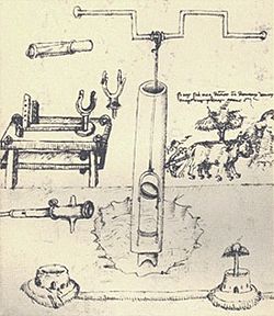 First European depiction of a piston pump, by Taccola, c. 1450[37]
 Irrigation is underway by pump-enabled extraction directly from the Gumti, seen in the background, in Comilla, Bangladesh.
One sort of pump once common worldwide was a hand-powered water pump, or 'pitcher pump'. It was commonly installed over community water wells in the days before piped water supplies.
In parts of the British Isles, it was often called the parish pump. Though such community pumps are no longer common, people still used the expression parish pump to describe a place or forum where matters of local interest are discussed.[38]
Because water from pitcher pumps is drawn directly from the soil, it is more prone to contamination. If such water is not filtered and purified, consumption of it might lead to gastrointestinal or other water-borne diseases. A notorious case is the 1854 Broad Street cholera outbreak. At the time it was not known how cholera was transmitted, but physician John Snow suspected contaminated water and had the handle of the public pump he suspected removed; the outbreak then subsided.
Modern hand-operated community pumps are considered the most sustainable low-cost option for safe water supply in resource-poor settings, often in rural areas in developing countries. A hand pump opens access to deeper groundwater that is often not polluted and also improves the safety of a well by protecting the water source from contaminated buckets. Pumps such as the Afridev pump are designed to be cheap to build and install, and easy to maintain with simple parts. However, scarcity of spare parts for these type of pumps in some regions of Africa has diminished their utility for these areas.
Sealing multiphase pumping applications
[edit]
Multiphase pumping applications, also referred to as tri-phase, have grown due to increased oil drilling activity. In addition, the economics of multiphase production is attractive to upstream operations as it leads to simpler, smaller in-field installations, reduced equipment costs and improved production rates. In essence, the multiphase pump can accommodate all fluid stream properties with one piece of equipment, which has a smaller footprint. Often, two smaller multiphase pumps are installed in series rather than having just one massive pump.
Types and features of multiphase pumps
[edit]
Helico-axial (centrifugal)
[edit]
A rotodynamic pump with one single shaft that requires two mechanical seals, this pump uses an open-type axial impeller. It is often called a Poseidon pump, and can be described as a cross between an axial compressor and a centrifugal pump.
Twin-screw (positive-displacement)
[edit]
The twin-screw pump is constructed of two inter-meshing screws that move the pumped fluid. Twin screw pumps are often used when pumping conditions contain high gas volume fractions and fluctuating inlet conditions. Four mechanical seals are required to seal the two shafts.
Progressive cavity (positive-displacement)
[edit]
Progressive Cavity Pumps are well suited to pump sludge, slurries, viscous, and shear sensitive fluids. [39] Progressive cavity pumps are single-screw types use in surface and downhole oil production.[40] They serve a vast arrange of industries and applications ranging from Wastewater Treatment,[41] Pulp and Paper, oil and gas, mining, and oil and gas.
Electric submersible (centrifugal)
[edit]
These pumps are basically multistage centrifugal pumps and are widely used in oil well applications as a method for artificial lift. These pumps are usually specified when the pumped fluid is mainly liquid.
Buffer tank A buffer tank is often installed upstream of the pump suction nozzle in case of a slug flow. The buffer tank breaks the energy of the liquid slug, smooths any fluctuations in the incoming flow and acts as a sand trap.
As the name indicates, multiphase pumps and their mechanical seals can encounter a large variation in service conditions such as changing process fluid composition, temperature variations, high and low operating pressures and exposure to abrasive/erosive media. The challenge is selecting the appropriate mechanical seal arrangement and support system to ensure maximized seal life and its overall effectiveness.[42][43][44]
Specifications
[edit]
Pumps are commonly rated by horsepower, volumetric flow rate, outlet pressure in metres (or feet) of head, inlet suction in suction feet (or metres) of head. The head can be simplified as the number of feet or metres the pump can raise or lower a column of water at atmospheric pressure.
From an initial design point of view, engineers often use a quantity termed the specific speed to identify the most suitable pump type for a particular combination of flow rate and head. Net Positive Suction Head (NPSH) is crucial for pump performance. It has two key aspects: 1) NPSHr (Required): The Head required for the pump to operate without cavitation issues. 2) NPSHa (Available): The actual pressure provided by the system (e.g., from an overhead tank). For optimal pump operation, NPSHa must always exceed NPSHr. This ensures the pump has enough pressure to prevent cavitation, a damaging condition.
Pumping power
[edit]
Main article: Bernoulli's equation
The power imparted into a fluid increases the energy of the fluid per unit volume. Thus the power relationship is between the conversion of the mechanical energy of the pump mechanism and the fluid elements within the pump. In general, this is governed by a series of simultaneous differential equations, known as the Navier–Stokes equations. However a more simple equation relating only the different energies in the fluid, known as Bernoulli's equation can be used. Hence the power, P, required by the pump:

where Δp is the change in total pressure between the inlet and outlet (in Pa), and Q, the volume flow-rate of the fluid is given in m3/s. The total pressure may have gravitational, static pressure and kinetic energy components; i.e. energy is distributed between change in the fluid's gravitational potential energy (going up or down hill), change in velocity, or change in static pressure. η is the pump efficiency, and may be given by the manufacturer's information, such as in the form of a pump curve, and is typically derived from either fluid dynamics simulation (i.e. solutions to the Navier–Stokes for the particular pump geometry), or by testing. The efficiency of the pump depends upon the pump's configuration and operating conditions (such as rotational speed, fluid density and viscosity etc.)

For a typical "pumping" configuration, the work is imparted on the fluid, and is thus positive. For the fluid imparting the work on the pump (i.e. a turbine), the work is negative. Power required to drive the pump is determined by dividing the output power by the pump efficiency. Furthermore, this definition encompasses pumps with no moving parts, such as a siphon.
Efficiency
[edit]
Pump efficiency is defined as the ratio of the power imparted on the fluid by the pump in relation to the power supplied to drive the pump. Its value is not fixed for a given pump, efficiency is a function of the discharge and therefore also operating head. For centrifugal pumps, the efficiency tends to increase with flow rate up to a point midway through the operating range (peak efficiency or Best Efficiency Point (BEP) ) and then declines as flow rates rise further. Pump performance data such as this is usually supplied by the manufacturer before pump selection. Pump efficiencies tend to decline over time due to wear (e.g. increasing clearances as impellers reduce in size).
When a system includes a centrifugal pump, an important design issue is matching the head loss-flow characteristic with the pump so that it operates at or close to the point of its maximum efficiency.
Pump efficiency is an important aspect and pumps should be regularly tested. Thermodynamic pump testing is one method.
Minimum flow protection
[edit]
Most large pumps have a minimum flow requirement below which the pump may be damaged by overheating, impeller wear, vibration, seal failure, drive shaft damage or poor performance.[45] A minimum flow protection system ensures that the pump is not operated below the minimum flow rate. The system protects the pump even if it is shut-in or dead-headed, that is, if the discharge line is completely closed.[46]
The simplest minimum flow system is a pipe running from the pump discharge line back to the suction line. This line is fitted with an orifice plate sized to allow the pump minimum flow to pass.[47] The arrangement ensures that the minimum flow is maintained, although it is wasteful as it recycles fluid even when the flow through the pump exceeds the minimum flow.
 Part of a process flow diagram of pump minimum flow protection arrangement
A more sophisticated, but more costly, system (see diagram) comprises a flow measuring device (FE) in the pump discharge which provides a signal into a flow controller (FIC) which actuates a flow control valve (FCV) in the recycle line. If the measured flow exceeds the minimum flow then the FCV is closed. If the measured flow falls below the minimum flow the FCV opens to maintain the minimum flowrate.[45]
As the fluids are recycled the kinetic energy of the pump increases the temperature of the fluid. For many pumps this added heat energy is dissipated through the pipework. However, for large industrial pumps, such as oil pipeline pumps, a recycle cooler is provided in the recycle line to cool the fluids to the normal suction temperature.[48] Alternatively the recycled fluids may be returned to upstream of the export cooler in an oil refinery, oil terminal, or offshore installation.
References
[edit]
- ^ a b Submersible slurry pumps in high demand. Engineeringnews.co.za. Retrieved on 2011-05-25.
- ^ TAXONOMY OF PUMPS AND WATER LIFTS. Fao.org. Retrieved on 2011-05-25.
- ^
Engineering Sciences Data Unit (2007). "Radial, mixed and axial flow pumps. Introduction" (PDF). Archived from the original (PDF) on 2014-03-08. Retrieved 2017-08-18.
- ^ "Understanding positive displacement pumps | PumpScout". Archived from the original on 2018-01-04. Retrieved 2018-01-03.
- ^ "The Volumetric Efficiency of Rotary Positive Displacement Pumps". www.pumpsandsystems.com. 2015-05-21. Retrieved 2019-03-27.
- ^ inc., elyk innovation. "Positive Displacement Pumps - LobePro Rotary Pumps". www.lobepro.com. Archived from the original on 2018-01-04. Retrieved 2018-01-03.
- ^ "Eccentric Disc Pumps". PSG.
- ^ "Hollow Disc Rotary Pumps". APEX Equipment. Archived from the original on 2020-08-06. Retrieved 2019-12-20.
- ^ "M Pompe | Hollow Oscillating Disk Pumps | self priming pumps | reversible pumps | low-speed pumps". www.mpompe.com. Archived from the original on 2020-02-06. Retrieved 2019-12-20.
- ^ "Hollow disc pumps". Pump Supplier Bedu.
- ^ "3P PRINZ - Hollow rotary disk pumps - Pompe 3P - Made in Italy". www.3pprinz.com. Archived from the original on 2020-08-06. Retrieved 2019-12-20.
- ^ "Hollow Disc Pump". magnatexpumps.com. Archived from the original on 2020-08-06. Retrieved 2019-12-20.
- ^ "Hollow Rotary Disc Pumps". November 4, 2014.
- ^ Inc., Triangle Pump Components. "What Is Volumetric Efficiency?". Retrieved 2018-01-03.
- ^ "FAQs and Favorites – Espresso Machines". www.home-barista.com. 21 November 2014.
- ^ "The Pump: The Heart of Your Espresso Machine". Clive Coffee.
- ^ "Definitive Guide: Pumps Used in Pressure Washers". The Pressure Washr Review. 13 August 2015. Retrieved May 14, 2016.
- ^ "Drilling Pumps". Gardner Denver.
- ^ "Stimulation and Fracturing pumps: Reciprocating, Quintuplex Stimulation and Fracturing Pump" Archived 2014-02-22 at the Wayback Machine. Gardner Denver.
- ^ "Advantages of an Air Operated Double Diaphragm Pump". Retrieved 2018-01-03.
- ^ Tanzania water Archived 2012-03-31 at the Wayback Machine blog – example of grassroots researcher telling about his study and work with the rope pump in Africa.
- ^ C.M. Schumacher, M. Loepfe, R. Fuhrer, R.N. Grass, and W.J. Stark, "3D printed lost-wax casted soft silicone monoblocks enable heart-inspired pumping by internal combustion," RSC Advances, Vol. 4, pp. 16039–16042, 2014.
- ^ Demirbas, Ayhan (2008-11-14). Biofuels: Securing the Planet's Future Energy Needs. Springer Science & Business Media. ISBN 9781848820111.
- ^ Welcome to the Hydraulic Institute Archived 2011-07-27 at the Wayback Machine. Pumps.org. Retrieved on 2011-05-25.
- ^ "Radial, mixed and axial flow pumps" (PDF). Institution of Diploma Marine Engineers, Bangladesh. June 2003. Archived from the original (PDF) on 2014-03-08. Retrieved 2017-08-18.
- ^ a b Quail F, Scanlon T, Stickland M (2011-01-11). "Design optimisation of a regenerative pump using numerical and experimental techniques" (PDF). International Journal of Numerical Methods for Heat & Fluid Flow. 21: 95–111. doi:10.1108/09615531111095094. Retrieved 2021-07-21.
- ^ a b "Regenerative Turbine Pump". rothpump.com. Retrieved 30 April 2021.
- ^ Rajmane, M. Satish; Kallurkar, S.P. (May 2015). "CFD Analysis of Domestic Centrifugal Pump for Performance Enhancement". International Research Journal of Engineering and Technology. 02 / #02. Retrieved 30 April 2021.
- ^ a b "Regenerative turbine pumps: product brochure" (PDF). PSG Dover: Ebsra. pp. 3-4-7. Retrieved 30 April 2021.
- ^ "Regenerative Turbine Pump vs Centrifugal Pump". Dyna Flow Engineering. Archived from the original on 30 April 2021. Retrieved 30 April 2021.
- ^ "What is a Side Channel Pump?". Michael Smith Engineers. Retrieved December 24, 2022.
- ^ a b Pump Statistics Should Shape Strategies Archived 2016-03-04 at the Wayback Machine. Mt-online.com 1 October 2008. Retrieved 24 September 2014.
- ^ Wasser, Goodenberger, Jim and Bob (November 1993). "Extended Life, Zero Emissions Seal for Process Pumps". John Crane Technical Report. Routledge. TRP 28017.
- ^ Nash (2017-01-20). NASH Liquid Ring Vacuum Pump - How It Works. Retrieved 2024-11-07 – via YouTube.
- ^ Donald Routledge Hill, "Mechanical Engineering in the Medieval Near East", Scientific American, May 1991, pp. 64-9 (cf. Donald Hill, Mechanical Engineering Archived 25 December 2007 at the Wayback Machine)
- ^ Ahmad Y. al-Hassan. "The Origin of the Suction Pump: al-Jazari 1206 A.D." Archived from the original on 26 February 2008. Retrieved 16 July 2008.
- ^ Hill, Donald Routledge (1996). A History of Engineering in Classical and Medieval Times. London: Routledge. p. 143. ISBN 0-415-15291-7.
- ^ "Online Dictionary – Parish Pump". Retrieved 2010-11-22.
- ^ Daniel, Alvarado. "Production Engineer". sulzer. Retrieved 6 March 2025.
- ^ Alvarado, Daniel. "Production Engineer". slb. Retrieved 6 March 2025.
- ^ Daniel, Alvarado (25 February 2025). "Production Engineer". ACCA Pumps. Retrieved 6 March 2025.
- ^ Sealing Multiphase Pumping Applications | Seals Archived 2009-09-03 at the Wayback Machine. Pump-zone.com. Retrieved on 2011-05-25.
- ^ John Crane Seal Sentinel – John Crane Increases Production Capabilities with Machine that Streamlines Four Machining Functions into One Archived 2010-11-27 at the Wayback Machine. Sealsentinel.com. Retrieved on 2011-05-25.
- ^ Vacuum pump new on SA market. Engineeringnews.co.za. Retrieved on 2011-05-25.
- ^ a b Crane Engineering. "minimum flow bypass line". Crane Engineering. Retrieved 25 January 2021.
- ^ Gas Processors Suppliers Association (2004). GPSA Engineering Data Book (12 ed.). Tulsa: GPSA. pp. Chapter 7 Pumps and hydraulic turbines.
- ^ Pump Industry (30 September 2020). "Four methods for maintaining minimum flow conditions". Pump Industry. Retrieved 25 January 2021.
- ^ Shell, Shearwater P&IDs dated 1997
Further reading
[edit]
- Australian Pump Manufacturers' Association. Australian Pump Technical Handbook, 3rd edition. Canberra: Australian Pump Manufacturers' Association, 1987. ISBN 0-7316-7043-4.
- Hicks, Tyler G. and Theodore W. Edwards. Pump Application Engineering. McGraw-Hill Book Company.1971. ISBN 0-07-028741-4
- Karassik, Igor, ed. (2007). Pump Handbook (4 ed.). McGraw Hill. ISBN 9780071460446.
- Robbins, L. B. "Homemade Water Pressure Systems". Popular Science, February 1919, pages 83–84. Article about how a homeowner can easily build a pressurized home water system that does not use electricity.
Wikimedia Commons has media related to Pumps.
Machines
| |
| Classical simple machines |
- Inclined plane
- Lever
- Pulley
- Screw
- Wedge
- Wheel and axle
|
| Clocks |
- Atomic clock
- Chronometer
- Pendulum clock
- Quartz clock
|
| Compressors and pumps |
- Archimedes' screw
- Eductor-jet pump
- Hydraulic ram
- Pump
- Trompe
- Vacuum pump
|
| External combustion engines |
- Steam engine
- Stirling engine
|
| Internal combustion engines |
- Gas turbine
- Reciprocating engine
- Rotary engine
- Nutating disc engine
|
| Linkages |
- Pantograph
- Peaucellier-Lipkin
|
| Turbine |
- Gas turbine
- Jet engine
- Steam turbine
- Water turbine
- Wind generator
- Windmill
|
| Aerofoil |
- Sail
- Wing
- Rudder
- Flap
- Propeller
|
| Electronics |
- Vacuum tube
- Transistor
- Diode
- Resistor
- Capacitor
- Inductor
|
| Vehicles |
|
| Miscellaneous |
- Mecha
- Robot
- Agricultural
- Seed-counting machine
- Vending machine
- Wind tunnel
- Check weighing machines
- Riveting machines
|
| Springs |
|
Authority control databases: National  |
- Germany
- United States
- France
- BnF data
- Japan
- Israel
|