How Material Expansion Restores Floor Elevation

How Material Expansion Restores Floor Elevation

Drilling Holes for Mudjacking

Understanding foundation settlement and its impact on floors is crucial when considering how material expansion can restore floor elevation. Foundation settlement occurs when the soil beneath a building compresses or shifts, causing the structure to sink unevenly. This can lead to noticeable issues like sloping floors, cracks in walls, and misaligned doors and windows. Over time, these symptoms not only affect the aesthetics of a home but also its structural integrity and safety.


When floors begin to settle, they lose their original levelness, which can be distressing for homeowners. However, an innovative approach to rectify this issue involves utilizing materials that expand. My house settling sounds so much more peaceful than the reality of my house slowly developing structural problems wall crack sealing Skokie clay. Materials like certain types of foam or expansive soils can be injected beneath the settled foundation. As these materials expand, they exert upward pressure, lifting the foundation back towards its original position.


This process of material expansion is particularly effective because it addresses the root cause of the problem - the void space created by soil settlement. By filling these voids with expanding material, not only is the floor elevation restored, but additional support is provided to prevent future settling. The beauty of this method lies in its non-invasive nature; often, it requires minimal disruption to the existing structure compared to traditional methods that might involve extensive excavation.


Moreover, restoring floor elevation through material expansion has long-term benefits. It helps maintain the value of the property by preserving its structural integrity and preventing further damage that could arise from uneven settling. Homeowners benefit from a more stable living environment where daily activities are not hindered by uneven floors.


In summary, understanding how foundation settlement impacts floors sets the stage for appreciating solutions like material expansion. This approach not only corrects current issues but also fortifies buildings against future problems, offering a practical and efficient restoration method that aligns with modern construction standards and homeowner expectations.

When it comes to restoring the elevation of floors that have settled or sunk over time, understanding the science behind material expansion is crucial. Material expansion, specifically in the context of floor lifting, involves injecting materials beneath the floor that expand upon introduction, thereby lifting and leveling the surface above. This process is not only innovative but rooted in fundamental principles of physics and chemistry.


The primary materials used for this purpose are polyurethane foams and certain types of cementitious grouts. Polyurethane, when injected as a liquid under low pressure, reacts with a catalyst or moisture from the soil to expand significantly. This expansion creates a high-density foam that fills voids and applies upward pressure on the floor, effectively raising it back to its original level or even higher if necessary.


The chemistry behind this reaction is fascinating. Polyurethane is formed through a polymerization process where two components, typically an isocyanate and a polyol, react exothermically. As they combine, they produce carbon dioxide gas as a byproduct which gets trapped within the polymer matrix, causing it to expand. This expansion can be controlled by adjusting the formulation of the chemicals used, allowing professionals to tailor the lift needed for specific scenarios.


Similarly, cementitious grouts work on slightly different principles but achieve similar results. These materials are often mixed with water or other additives that cause them to swell upon setting. The expansion here is due to hydration reactions where water molecules interact with cement particles leading to an increase in volume.


This scientific approach not only restores floors but does so with precision and minimal disturbance to existing structures. Its particularly beneficial because it addresses underlying issues like soil compaction or erosion without invasive construction methods. Moreover, these materials once set provide additional structural support, enhancing the longevity of the repair.


In essence, material expansion for floor lifting leverages basic scientific principles in a practical application that showcases how chemistry and physics can solve real-world problems elegantly. By understanding and harnessing these expansions, we ensure our living spaces remain functional and safe over time, demonstrating yet again how science underpins everyday solutions in construction and restoration.

Injecting the Slurry into the Foundation

Lets talk about how we lift floors back up when theyve sunk, using materials that, well, expand. Think of it like filling a void, but instead of just dumping something in there, were using materials that grow to gently push things back into place.


One common method involves polyurethane foams. These arent your average packing peanuts! These are specially formulated, two-part mixtures that, when combined, react to create a rigid foam. As the foam expands, it fills the gaps beneath the foundation and gently lifts the settled concrete slab back towards its original position. The beauty of polyurethane is its controlled expansion. We can inject it strategically and monitor the lift, ensuring we dont overcorrect. Plus, its relatively lightweight, so it doesnt add a huge amount of extra weight to the soil.


Another rising star (pun intended!) is expanding grout. Unlike traditional grout, which is more about filling cracks, expanding grout is designed to, you guessed it, expand! This expansion is usually achieved through chemical reactions within the grout mixture. Its often used in situations where the soil is compacted or theres a need for more structural support alongside the lifting action. Expanding grout is typically denser and stronger than polyurethane foam, making it a good choice for heavier loads or more challenging soil conditions.


Finally, sometimes we use a method called slab jacking or mudjacking, which involves injecting a mixture of cement, soil, sand, and other additives under the slab. While the material itself doesnt necessarily "expand" in the same way as foam or grout, the sheer volume of the injected material fills voids and effectively lifts the slab. The pressure from the injection process, coupled with the carefully chosen mixture, allows for controlled and precise elevation.


So, whether its the reactive power of polyurethane, the structural strength of expanding grout, or the volumetric force of mudjacking, these expandable materials are key players in the delicate art of restoring floor elevation. They allow us to address foundation settlement without resorting to more invasive and disruptive methods, bringing homes back to level and stability.

Injecting the Slurry into the Foundation

Finishing and Cleanup Post-Fill

Okay, so youre wondering how "material expansion" can actually lift a sunken floor, right? Think of it like this: your floors gone down, maybe because the ground underneath shifted or compacted. Now, were not talking about magic here; were talking about strategically using materials that, when coaxed, get bigger.


The "Material Expansion Process" – lets break it down step-by-step, keeping it real.


First, Assessment and Preparation: Before anything, you gotta figure out why the floor sank in the first place. Is it a leaky pipe? Bad soil? Address the root cause or itll just happen again. Then, the area under the floor needs to be prepped. This usually involves drilling small, strategically placed holes through the floor. Think of them like little access points.


Second, Material Injection: This is where the expanding material comes in. Typically, its a specialized type of expanding polyurethane foam (or sometimes even a cement-based grout that expands). This material is injected through those holes we drilled. Its not just dumped in; its carefully pumped in under controlled pressure. That pressure is key.


Third, Expansion and Lifting: As the material is injected, it starts to expand. Think of it like yeast in bread dough, but much, much faster and more powerful. This expansion is what does the heavy lifting (literally). The expanding material fills any voids underneath the floor, and as it keeps expanding, it starts to gently push the floor back up towards its original position.


Fourth, Monitoring and Adjustment: This isn't a "set it and forget it" kind of deal. During the injection and expansion process, the floors elevation is constantly monitored. Lasers, levels, the whole shebang. The goal is to lift the floor evenly and prevent any cracking or further damage. The amount of material injected, and the pressure used, are adjusted on the fly based on these readings.


Fifth, Curing and Finishing: Once the floor is back where it needs to be (or as close as safely possible), the expanding material is allowed to fully cure and harden. This creates a solid, stable base underneath the floor. Finally, those injection holes are patched up, and the floor is finished to blend seamlessly with the existing surface.


Essentially, the material expansion process is like a carefully orchestrated ballet of lifting and support. Its not a quick fix, but a controlled and precise method to restore a sunken floor elevation by strategically using expanding materials. Its all about understanding the materials, controlling the pressure, and constantly monitoring the results.

In the realm of structural engineering and renovation, the concept of material expansion to restore floor elevation has emerged as a fascinating solution to a common problem faced by many old buildings: sagging or uneven floors. This technique involves using materials that expand over time or under specific conditions to lift and level floors that have settled or slumped due to various reasons like foundation issues, moisture changes, or simply the passage of time.


One particularly successful case study involves a historic building in Charleston, South Carolina, built in the early 19th century. Over the years, this building had developed significant floor unevenness, with some areas dipping noticeably lower than others. Traditional methods like underpinning or complete floor replacement would have been not only costly but also potentially detrimental to the buildings historical integrity.


The solution came through innovative use of expansive grout technology. This grout mixture was specifically engineered to expand upon curing, exerting upward pressure on the floor above it. The process began with careful assessment and mapping of the floor levels using laser leveling technology to identify where elevation was most needed. Following this, small holes were drilled into strategic points beneath the floor where support beams met the foundation.


Once these preparations were complete, the expansive grout was injected into these drilled points. As it cured, it expanded slowly over several days, gently lifting the floor back towards its original level without causing any damage or stress to the structure above. This gradual expansion was key; it allowed for precise control over how much lift was achieved at each point, ensuring an even restoration across the entire floor area.


Another notable example comes from a mid-20th-century school in Seattle where wooden floors had become uneven due to moisture variations affecting soil stability below. Here again, after evaluating different options including traditional jacking systems which could be disruptive during school hours, expansive materials proved superior. A polyurethane-based foam was chosen for its excellent expansion properties when mixed with water and its ability to fill voids effectively beneath wooden structures.


In this scenario, technicians injected this foam under low pressure through small access points cut into the flooring from below in unoccupied spaces like basements or crawl spaces. The foam expanded rapidly but controllably within minutes, pushing up against wooden joists and subflooring until they reached desired elevations monitored by real-time leveling devices.


Both cases illustrate how modern material science can provide elegant solutions that respect both functionality and historical value or operational continuity of buildings. By choosing materials that expand predictably and controllably, engineers can restore floor elevations with minimal disturbance compared to more invasive methods. These successful restorations highlight not only technical ingenuity but also a commitment to preserving architectural heritage while addressing practical needs effectively through sustainable practices in construction renovation techniques todays era demands from us all involved fields craftsmanship engineering alike ensure longevity our built environments while adapting them meet contemporary standards safety usability aesthetics alike bringing past present future together seamless harmony through such projects truly remarkable achievements field restoration indeed!

Okay, lets talk about how material expansion techniques can help bring a floor back up to where it should be. Basically, were talking about using materials that, when treated in a certain way, get bigger and lift things. Its a neat trick, but like anything, its got its good sides and its not-so-good sides.


On the plus side, material expansion can be a relatively non-invasive way to raise a floor. Imagine a situation where you've got a sunken area, maybe due to soil settlement or some other structural issue. Instead of tearing everything up and rebuilding, you might be able to inject an expanding foam or grout underneath. The expansion lifts the floor gently and evenly, hopefully minimizing damage to existing structures and finishes. This can save time, money, and a whole lot of dust and disruption. Plus, some of these materials can fill voids and stabilize the ground underneath, addressing the root cause of the problem. They can also be quite precise; you can often control the expansion rate and amount, allowing for fine-tuning the lift and ensuring a level surface.


However, it's not all sunshine and roses. There are downsides to consider. First off, the success of this method really depends on the underlying problem. If the issue is severe structural damage, simply lifting the floor won't fix the core problem. It's more of a cosmetic fix, and the floor might sink again if the underlying issues aren't addressed. Secondly, the expanding materials themselves can be problematic. Some foams, for example, can be sensitive to moisture or temperature changes, which could affect their long-term stability. Also, the expansion process can sometimes cause cracking or damage to existing floor finishes, especially if the lift is too rapid or uneven. Choosing the right material and a skilled application team is absolutely critical. Finally, cost can be a factor. While sometimes cheaper than total replacement, specialized materials and equipment, along with experienced technicians, can still make it a pricey undertaking. So, you really need to weigh the potential savings against the risks and the long-term viability of the solution. Its all about understanding the specific situation and making an informed decision.

Okay, lets talk about fixing wonky floors. For ages, when a floor started to sag or dip, the traditional answer was basically brute force. Think shims, self-leveling compounds, maybe even jacking the whole shebang up and re-laying it. These methods, while sometimes necessary, can be messy, disruptive, and frankly, a bit like treating a symptom instead of the cause. They often involve significant demolition, dust everywhere, and a lot of waiting for things to dry or cure.


Now, enter the idea of using controlled material expansion to restore floor elevation. This is a newer approach, and its pretty fascinating. Imagine injecting a specifically engineered material beneath the floor that, when it expands, gently lifts the sunken area back into place. Its like strategically giving the floor a little boost where it needs it most.


The key difference is the invasiveness (or lack thereof). Traditional methods often tear things apart, requiring significant rebuilding. Material expansion, on the other hand, can be a much more targeted and minimally invasive solution. It's often quicker too, meaning less disruption to your daily life. Think less jackhammering, more… precision lifting.


Of course, its not a perfect solution for every situation. Severely damaged subfloors or structural issues might still require more traditional approaches. But for many cases of settling or minor elevation problems, material expansion offers a compelling alternative. It's a way of addressing the issue at a deeper level, aiming to restore the floors original level without the chaos and upheaval of older methods. Its a clever application of materials science to a very common problem.


Cement powder in a bag, ready to be mixed with aggregates and water.[1]
Cement block construction examples from the Multiplex Manufacturing Company of Toledo, Ohio, in 1905

A cement is a binder, a chemical substance used for construction that sets, hardens, and adheres to other materials to bind them together. Cement is seldom used on its own, but rather to bind sand and gravel (aggregate) together. Cement mixed with fine aggregate produces mortar for masonry, or with sand and gravel, produces concrete. Concrete is the most widely used material in existence and is behind only water as the planet's most-consumed resource.[2]

Cements used in construction are usually inorganic, often lime- or calcium silicate-based, and are either hydraulic or less commonly non-hydraulic, depending on the ability of the cement to set in the presence of water (see hydraulic and non-hydraulic lime plaster).

Hydraulic cements (e.g., Portland cement) set and become adhesive through a chemical reaction between the dry ingredients and water. The chemical reaction results in mineral hydrates that are not very water-soluble. This allows setting in wet conditions or under water and further protects the hardened material from chemical attack. The chemical process for hydraulic cement was found by ancient Romans who used volcanic ash (pozzolana) with added lime (calcium oxide).

Non-hydraulic cement (less common) does not set in wet conditions or under water. Rather, it sets as it dries and reacts with carbon dioxide in the air. It is resistant to attack by chemicals after setting.

The word "cement" can be traced back to the Ancient Roman term opus caementicium, used to describe masonry resembling modern concrete that was made from crushed rock with burnt lime as binder.[3] The volcanic ash and pulverized brick supplements that were added to the burnt lime, to obtain a hydraulic binder, were later referred to as cementum, cimentum, cäment, and cement. In modern times, organic polymers are sometimes used as cements in concrete.

World production of cement is about 4.4 billion tonnes per year (2021, estimation),[4][5] of which about half is made in China, followed by India and Vietnam.[4][6]

The cement production process is responsible for nearly 8% (2018) of global CO2 emissions,[5] which includes heating raw materials in a cement kiln by fuel combustion and release of CO2 stored in the calcium carbonate (calcination process). Its hydrated products, such as concrete, gradually reabsorb atmospheric CO2 (carbonation process), compensating for approximately 30% of the initial CO2 emissions.[7]

Chemistry

[edit]

Cement materials can be classified into two distinct categories: hydraulic cements and non-hydraulic cements according to their respective setting and hardening mechanisms. Hydraulic cement setting and hardening involves hydration reactions and therefore requires water, while non-hydraulic cements only react with a gas and can directly set under air.

Hydraulic cement

[edit]
Clinker nodules produced by sintering at 1450 °C

By far the most common type of cement is hydraulic cement, which hardens by hydration (when water is added) of the clinker minerals. Hydraulic cements (such as Portland cement) are made of a mixture of silicates and oxides, the four main mineral phases of the clinker, abbreviated in the cement chemist notation, being:

C3S: alite (3CaO·SiO2);
C2S: belite (2CaO·SiO2);
C3A: tricalcium aluminate (3CaO·Al2O3) (historically, and still occasionally, called celite);
C4AF: brownmillerite (4CaO·Al2O3·Fe2O3).

The silicates are responsible for the cement's mechanical properties — the tricalcium aluminate and brownmillerite are essential for the formation of the liquid phase during the sintering (firing) process of clinker at high temperature in the kiln. The chemistry of these reactions is not completely clear and is still the object of research.[8]

First, the limestone (calcium carbonate) is burned to remove its carbon, producing lime (calcium oxide) in what is known as a calcination reaction. This single chemical reaction is a major emitter of global carbon dioxide emissions.[9]

The lime reacts with silicon dioxide to produce dicalcium silicate and tricalcium silicate.

The lime also reacts with aluminium oxide to form tricalcium aluminate.

In the last step, calcium oxide, aluminium oxide, and ferric oxide react together to form brownmillerite.

Non-hydraulic cement

[edit]
Calcium oxide obtained by thermal decomposition of calcium carbonate at high temperature (above 825 °C).

A less common form of cement is non-hydraulic cement, such as slaked lime (calcium oxide mixed with water), which hardens by carbonation in contact with carbon dioxide, which is present in the air (~ 412 vol. ppm ≃ 0.04 vol. %). First calcium oxide (lime) is produced from calcium carbonate (limestone or chalk) by calcination at temperatures above 825 °C (1,517 °F) for about 10 hours at atmospheric pressure:

The calcium oxide is then spent (slaked) by mixing it with water to make slaked lime (calcium hydroxide):

Once the excess water is completely evaporated (this process is technically called setting), the carbonation starts:

This reaction is slow, because the partial pressure of carbon dioxide in the air is low (~ 0.4 millibar). The carbonation reaction requires that the dry cement be exposed to air, so the slaked lime is a non-hydraulic cement and cannot be used under water. This process is called the lime cycle.

History

[edit]

Perhaps the earliest known occurrence of cement is from twelve million years ago. A deposit of cement was formed after an occurrence of oil shale located adjacent to a bed of limestone burned by natural causes. These ancient deposits were investigated in the 1960s and 1970s.[10]

Alternatives to cement used in antiquity

[edit]

Cement, chemically speaking, is a product that includes lime as the primary binding ingredient, but is far from the first material used for cementation. The Babylonians and Assyrians used bitumen (asphalt or pitch) to bind together burnt brick or alabaster slabs. In Ancient Egypt, stone blocks were cemented together with a mortar made of sand and roughly burnt gypsum (CaSO4 · 2H2O), which is plaster of Paris, which often contained calcium carbonate (CaCO3),[11]

Ancient Greece and Rome

[edit]

Lime (calcium oxide) was used on Crete and by the Ancient Greeks. There is evidence that the Minoans of Crete used crushed potsherds as an artificial pozzolan for hydraulic cement.[11] Nobody knows who first discovered that a combination of hydrated non-hydraulic lime and a pozzolan produces a hydraulic mixture (see also: Pozzolanic reaction), but such concrete was used by the Greeks, specifically the Ancient Macedonians,[12][13] and three centuries later on a large scale by Roman engineers.[14][15][16]

There is... a kind of powder which from natural causes produces astonishing results. It is found in the neighborhood of Baiae and in the country belonging to the towns round about Mount Vesuvius. This substance when mixed with lime and rubble not only lends strength to buildings of other kinds but even when piers of it are constructed in the sea, they set hard underwater.

— Marcus Vitruvius Pollio, Liber II, De Architectura, Chapter VI "Pozzolana" Sec. 1

The Greeks used volcanic tuff from the island of Thera as their pozzolan and the Romans used crushed volcanic ash (activated aluminium silicates) with lime. This mixture could set under water, increasing its resistance to corrosion like rust.[17] The material was called pozzolana from the town of Pozzuoli, west of Naples where volcanic ash was extracted.[18] In the absence of pozzolanic ash, the Romans used powdered brick or pottery as a substitute and they may have used crushed tiles for this purpose before discovering natural sources near Rome.[11] The huge dome of the Pantheon in Rome and the massive Baths of Caracalla are examples of ancient structures made from these concretes, many of which still stand.[19][2] The vast system of Roman aqueducts also made extensive use of hydraulic cement.[20] Roman concrete was rarely used on the outside of buildings. The normal technique was to use brick facing material as the formwork for an infill of mortar mixed with an aggregate of broken pieces of stone, brick, potsherds, recycled chunks of concrete, or other building rubble.[21]

Mesoamerica

[edit]

Lightweight concrete was designed and used for the construction of structural elements by the pre-Columbian builders who lived in a very advanced civilisation in El Tajin near Mexico City, in Mexico. A detailed study of the composition of the aggregate and binder show that the aggregate was pumice and the binder was a pozzolanic cement made with volcanic ash and lime.[22]

Middle Ages

[edit]

Any preservation of this knowledge in literature from the Middle Ages is unknown, but medieval masons and some military engineers actively used hydraulic cement in structures such as canals, fortresses, harbors, and shipbuilding facilities.[23][24] A mixture of lime mortar and aggregate with brick or stone facing material was used in the Eastern Roman Empire as well as in the West into the Gothic period. The German Rhineland continued to use hydraulic mortar throughout the Middle Ages, having local pozzolana deposits called trass.[21]

16th century

[edit]

Tabby is a building material made from oyster shell lime, sand, and whole oyster shells to form a concrete. The Spanish introduced it to the Americas in the sixteenth century.[25]

18th century

[edit]

The technical knowledge for making hydraulic cement was formalized by French and British engineers in the 18th century.[23]

John Smeaton made an important contribution to the development of cements while planning the construction of the third Eddystone Lighthouse (1755–59) in the English Channel now known as Smeaton's Tower. He needed a hydraulic mortar that would set and develop some strength in the twelve-hour period between successive high tides. He performed experiments with combinations of different limestones and additives including trass and pozzolanas[11] and did exhaustive market research on the available hydraulic limes, visiting their production sites, and noted that the "hydraulicity" of the lime was directly related to the clay content of the limestone used to make it. Smeaton was a civil engineer by profession, and took the idea no further.

In the South Atlantic seaboard of the United States, tabby relying on the oyster-shell middens of earlier Native American populations was used in house construction from the 1730s to the 1860s.[25]

In Britain particularly, good quality building stone became ever more expensive during a period of rapid growth, and it became a common practice to construct prestige buildings from the new industrial bricks, and to finish them with a stucco to imitate stone. Hydraulic limes were favored for this, but the need for a fast set time encouraged the development of new cements. Most famous was Parker's "Roman cement".[26] This was developed by James Parker in the 1780s, and finally patented in 1796. It was, in fact, nothing like material used by the Romans, but was a "natural cement" made by burning septaria – nodules that are found in certain clay deposits, and that contain both clay minerals and calcium carbonate. The burnt nodules were ground to a fine powder. This product, made into a mortar with sand, set in 5–15 minutes. The success of "Roman cement" led other manufacturers to develop rival products by burning artificial hydraulic lime cements of clay and chalk. Roman cement quickly became popular but was largely replaced by Portland cement in the 1850s.[11]

19th century

[edit]

Apparently unaware of Smeaton's work, the same principle was identified by Frenchman Louis Vicat in the first decade of the nineteenth century. Vicat went on to devise a method of combining chalk and clay into an intimate mixture, and, burning this, produced an "artificial cement" in 1817[27] considered the "principal forerunner"[11] of Portland cement and "...Edgar Dobbs of Southwark patented a cement of this kind in 1811."[11]

In Russia, Egor Cheliev created a new binder by mixing lime and clay. His results were published in 1822 in his book A Treatise on the Art to Prepare a Good Mortar published in St. Petersburg. A few years later in 1825, he published another book, which described various methods of making cement and concrete, and the benefits of cement in the construction of buildings and embankments.[28][29]

William Aspdin is considered the inventor of "modern" Portland cement.[30]

Portland cement, the most common type of cement in general use around the world as a basic ingredient of concrete, mortar, stucco, and non-speciality grout, was developed in England in the mid 19th century, and usually originates from limestone. James Frost produced what he called "British cement" in a similar manner around the same time, but did not obtain a patent until 1822.[31] In 1824, Joseph Aspdin patented a similar material, which he called Portland cement, because the render made from it was in color similar to the prestigious Portland stone quarried on the Isle of Portland, Dorset, England. However, Aspdins' cement was nothing like modern Portland cement but was a first step in its development, called a proto-Portland cement.[11] Joseph Aspdins' son William Aspdin had left his father's company and in his cement manufacturing apparently accidentally produced calcium silicates in the 1840s, a middle step in the development of Portland cement. William Aspdin's innovation was counterintuitive for manufacturers of "artificial cements", because they required more lime in the mix (a problem for his father), a much higher kiln temperature (and therefore more fuel), and the resulting clinker was very hard and rapidly wore down the millstones, which were the only available grinding technology of the time. Manufacturing costs were therefore considerably higher, but the product set reasonably slowly and developed strength quickly, thus opening up a market for use in concrete. The use of concrete in construction grew rapidly from 1850 onward, and was soon the dominant use for cements. Thus Portland cement began its predominant role. Isaac Charles Johnson further refined the production of meso-Portland cement (middle stage of development) and claimed he was the real father of Portland cement.[32]

Setting time and "early strength" are important characteristics of cements. Hydraulic limes, "natural" cements, and "artificial" cements all rely on their belite (2 CaO · SiO2, abbreviated as C2S) content for strength development. Belite develops strength slowly. Because they were burned at temperatures below 1,250 °C (2,280 °F), they contained no alite (3 CaO · SiO2, abbreviated as C3S), which is responsible for early strength in modern cements. The first cement to consistently contain alite was made by William Aspdin in the early 1840s: This was what we call today "modern" Portland cement. Because of the air of mystery with which William Aspdin surrounded his product, others (e.g., Vicat and Johnson) have claimed precedence in this invention, but recent analysis[33] of both his concrete and raw cement have shown that William Aspdin's product made at Northfleet, Kent was a true alite-based cement. However, Aspdin's methods were "rule-of-thumb": Vicat is responsible for establishing the chemical basis of these cements, and Johnson established the importance of sintering the mix in the kiln.

In the US the first large-scale use of cement was Rosendale cement, a natural cement mined from a massive deposit of dolomite discovered in the early 19th century near Rosendale, New York. Rosendale cement was extremely popular for the foundation of buildings (e.g., Statue of Liberty, Capitol Building, Brooklyn Bridge) and lining water pipes.[34] Sorel cement, or magnesia-based cement, was patented in 1867 by the Frenchman Stanislas Sorel.[35] It was stronger than Portland cement but its poor water resistance (leaching) and corrosive properties (pitting corrosion due to the presence of leachable chloride anions and the low pH (8.5–9.5) of its pore water) limited its use as reinforced concrete for building construction.[36]

The next development in the manufacture of Portland cement was the introduction of the rotary kiln. It produced a clinker mixture that was both stronger, because more alite (C3S) is formed at the higher temperature it achieved (1450 °C), and more homogeneous. Because raw material is constantly fed into a rotary kiln, it allowed a continuous manufacturing process to replace lower capacity batch production processes.[11]

20th century

[edit]
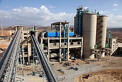
The National Cement Share Company of Ethiopia's new plant in Dire Dawa

Calcium aluminate cements were patented in 1908 in France by Jules Bied for better resistance to sulfates.[37] Also in 1908, Thomas Edison experimented with pre-cast concrete in houses in Union, N.J.[38]

In the US, after World War One, the long curing time of at least a month for Rosendale cement made it unpopular for constructing highways and bridges, and many states and construction firms turned to Portland cement. Because of the switch to Portland cement, by the end of the 1920s only one of the 15 Rosendale cement companies had survived. But in the early 1930s, builders discovered that, while Portland cement set faster, it was not as durable, especially for highways—to the point that some states stopped building highways and roads with cement. Bertrain H. Wait, an engineer whose company had helped construct the New York City's Catskill Aqueduct, was impressed with the durability of Rosendale cement, and came up with a blend of both Rosendale and Portland cements that had the good attributes of both. It was highly durable and had a much faster setting time. Wait convinced the New York Commissioner of Highways to construct an experimental section of highway near New Paltz, New York, using one sack of Rosendale to six sacks of Portland cement. It was a success, and for decades the Rosendale-Portland cement blend was used in concrete highway and concrete bridge construction.[34]

Cementitious materials have been used as a nuclear waste immobilizing matrix for more than a half-century.[39] Technologies of waste cementation have been developed and deployed at industrial scale in many countries. Cementitious wasteforms require a careful selection and design process adapted to each specific type of waste to satisfy the strict waste acceptance criteria for long-term storage and disposal.[40]

Types

[edit]
Components of cement:
comparison of chemical and physical characteristics[a][41][42][43]
Property Portland
cement
Siliceous[b]
fly ash
Calcareous[c]
fly ash
Slag
cement
Silica
fume
Proportion by mass (%)
SiO2 21.9 52 35 35 85–97
Al2O3 6.9 23 18 12
Fe2O3 3 11 6 1
CaO 63 5 21 40 < 1
MgO 2.5
SO3 1.7
Specific surface (m2/kg)[d] 370 420 420 400 15,000
– 30,000
Specific gravity 3.15 2.38 2.65 2.94 2.22
General purpose Primary binder Cement replacement Cement replacement Cement replacement Property enhancer
  1. ^ Values shown are approximate: those of a specific material may vary.
  2. ^ ASTM C618 Class F
  3. ^ ASTM C618 Class C
  4. ^ Specific surface measurements for silica fume by nitrogen adsorption (BET) method, others by air permeability method (Blaine).

Modern development of hydraulic cement began with the start of the Industrial Revolution (around 1800), driven by three main needs:

  • Hydraulic cement render (stucco) for finishing brick buildings in wet climates
  • Hydraulic mortars for masonry construction of harbor works, etc., in contact with sea water
  • Development of strong concretes

Modern cements are often Portland cement or Portland cement blends, but other cement blends are used in some industrial settings.

Portland cement

[edit]

Portland cement, a form of hydraulic cement, is by far the most common type of cement in general use around the world. This cement is made by heating limestone (calcium carbonate) with other materials (such as clay) to 1,450 °C (2,640 °F) in a kiln, in a process known as calcination that liberates a molecule of carbon dioxide from the calcium carbonate to form calcium oxide, or quicklime, which then chemically combines with the other materials in the mix to form calcium silicates and other cementitious compounds. The resulting hard substance, called 'clinker', is then ground with a small amount of gypsum ( CaSO4·2H2O) into a powder to make ordinary Portland cement, the most commonly used type of cement (often referred to as OPC). Portland cement is a basic ingredient of concrete, mortar, and most non-specialty grout. The most common use for Portland cement is to make concrete. Portland cement may be grey or white.

Portland cement blend

[edit]

Portland cement blends are often available as inter-ground mixtures from cement producers, but similar formulations are often also mixed from the ground components at the concrete mixing plant.

Portland blast-furnace slag cement, or blast furnace cement (ASTM C595 and EN 197-1 nomenclature respectively), contains up to 95% ground granulated blast furnace slag, with the rest Portland clinker and a little gypsum. All compositions produce high ultimate strength, but as slag content is increased, early strength is reduced, while sulfate resistance increases and heat evolution diminishes. Used as an economic alternative to Portland sulfate-resisting and low-heat cements.

Portland-fly ash cement contains up to 40% fly ash under ASTM standards (ASTM C595), or 35% under EN standards (EN 197–1). The fly ash is pozzolanic, so that ultimate strength is maintained. Because fly ash addition allows a lower concrete water content, early strength can also be maintained. Where good quality cheap fly ash is available, this can be an economic alternative to ordinary Portland cement.[44]

Portland pozzolan cement includes fly ash cement, since fly ash is a pozzolan, but also includes cements made from other natural or artificial pozzolans. In countries where volcanic ashes are available (e.g., Italy, Chile, Mexico, the Philippines), these cements are often the most common form in use. The maximum replacement ratios are generally defined as for Portland-fly ash cement.

Portland silica fume cement. Addition of silica fume can yield exceptionally high strengths, and cements containing 5–20% silica fume are occasionally produced, with 10% being the maximum allowed addition under EN 197–1. However, silica fume is more usually added to Portland cement at the concrete mixer.[45]

Masonry cements are used for preparing bricklaying mortars and stuccos, and must not be used in concrete. They are usually complex proprietary formulations containing Portland clinker and a number of other ingredients that may include limestone, hydrated lime, air entrainers, retarders, waterproofers, and coloring agents. They are formulated to yield workable mortars that allow rapid and consistent masonry work. Subtle variations of masonry cement in North America are plastic cements and stucco cements. These are designed to produce a controlled bond with masonry blocks.

Expansive cements contain, in addition to Portland clinker, expansive clinkers (usually sulfoaluminate clinkers), and are designed to offset the effects of drying shrinkage normally encountered in hydraulic cements. This cement can make concrete for floor slabs (up to 60 m square) without contraction joints.

White blended cements may be made using white clinker (containing little or no iron) and white supplementary materials such as high-purity metakaolin. Colored cements serve decorative purposes. Some standards allow the addition of pigments to produce colored Portland cement. Other standards (e.g., ASTM) do not allow pigments in Portland cement, and colored cements are sold as blended hydraulic cements.

Very finely ground cements are cement mixed with sand or with slag or other pozzolan type minerals that are extremely finely ground together. Such cements can have the same physical characteristics as normal cement but with 50% less cement, particularly because there is more surface area for the chemical reaction. Even with intensive grinding they can use up to 50% less energy (and thus less carbon emissions) to fabricate than ordinary Portland cements.[46]

Other

[edit]

Pozzolan-lime cements are mixtures of ground pozzolan and lime. These are the cements the Romans used, and are present in surviving Roman structures like the Pantheon in Rome. They develop strength slowly, but their ultimate strength can be very high. The hydration products that produce strength are essentially the same as those in Portland cement.

Slag-lime cements—ground granulated blast-furnace slag—are not hydraulic on their own, but are "activated" by addition of alkalis, most economically using lime. They are similar to pozzolan lime cements in their properties. Only granulated slag (i.e., water-quenched, glassy slag) is effective as a cement component.

Supersulfated cements contain about 80% ground granulated blast furnace slag, 15% gypsum or anhydrite and a little Portland clinker or lime as an activator. They produce strength by formation of ettringite, with strength growth similar to a slow Portland cement. They exhibit good resistance to aggressive agents, including sulfate.

Calcium aluminate cements are hydraulic cements made primarily from limestone and bauxite. The active ingredients are monocalcium aluminate CaAl2O4 (CaO · Al2O3 or CA in cement chemist notation, CCN) and mayenite Ca12Al14O33 (12 CaO · 7 Al2O3, or C12A7 in CCN). Strength forms by hydration to calcium aluminate hydrates. They are well-adapted for use in refractory (high-temperature resistant) concretes, e.g., for furnace linings.

Calcium sulfoaluminate cements are made from clinkers that include ye'elimite (Ca4(AlO2)6SO4 or C4A3S in Cement chemist's notation) as a primary phase. They are used in expansive cements, in ultra-high early strength cements, and in "low-energy" cements. Hydration produces ettringite, and specialized physical properties (such as expansion or rapid reaction) are obtained by adjustment of the availability of calcium and sulfate ions. Their use as a low-energy alternative to Portland cement has been pioneered in China, where several million tonnes per year are produced.[47][48] Energy requirements are lower because of the lower kiln temperatures required for reaction, and the lower amount of limestone (which must be endothermically decarbonated) in the mix. In addition, the lower limestone content and lower fuel consumption leads to a CO
2
emission around half that associated with Portland clinker. However, SO2 emissions are usually significantly higher.

"Natural" cements corresponding to certain cements of the pre-Portland era, are produced by burning argillaceous limestones at moderate temperatures. The level of clay components in the limestone (around 30–35%) is such that large amounts of belite (the low-early strength, high-late strength mineral in Portland cement) are formed without the formation of excessive amounts of free lime. As with any natural material, such cements have highly variable properties.

Geopolymer cements are made from mixtures of water-soluble alkali metal silicates, and aluminosilicate mineral powders such as fly ash and metakaolin.

Polymer cements are made from organic chemicals that polymerise. Producers often use thermoset materials. While they are often significantly more expensive, they can give a water proof material that has useful tensile strength.

Sorel cement is a hard, durable cement made by combining magnesium oxide and a magnesium chloride solution

Fiber mesh cement or fiber reinforced concrete is cement that is made up of fibrous materials like synthetic fibers, glass fibers, natural fibers, and steel fibers. This type of mesh is distributed evenly throughout the wet concrete. The purpose of fiber mesh is to reduce water loss from the concrete as well as enhance its structural integrity.[49] When used in plasters, fiber mesh increases cohesiveness, tensile strength, impact resistance, and to reduce shrinkage; ultimately, the main purpose of these combined properties is to reduce cracking.[50]

Electric cement is proposed to be made by recycling cement from demolition wastes in an electric arc furnace as part of a steelmaking process. The recycled cement is intended to be used to replace part or all of the lime used in steelmaking, resulting in a slag-like material that is similar in mineralogy to Portland cement, eliminating most of the associated carbon emissions.[51]

Setting, hardening and curing

[edit]

Cement starts to set when mixed with water, which causes a series of hydration chemical reactions. The constituents slowly hydrate and the mineral hydrates solidify and harden. The interlocking of the hydrates gives cement its strength. Contrary to popular belief, hydraulic cement does not set by drying out — proper curing requires maintaining the appropriate moisture content necessary for the hydration reactions during the setting and the hardening processes. If hydraulic cements dry out during the curing phase, the resulting product can be insufficiently hydrated and significantly weakened. A minimum temperature of 5 °C is recommended, and no more than 30 °C.[52] The concrete at young age must be protected against water evaporation due to direct insolation, elevated temperature, low relative humidity and wind.

The interfacial transition zone (ITZ) is a region of the cement paste around the aggregate particles in concrete. In the zone, a gradual transition in the microstructural features occurs.[53] This zone can be up to 35 micrometer wide.[54]: 351  Other studies have shown that the width can be up to 50 micrometer. The average content of unreacted clinker phase decreases and porosity decreases towards the aggregate surface. Similarly, the content of ettringite increases in ITZ. [54]: 352 

Safety issues

[edit]

Bags of cement routinely have health and safety warnings printed on them because not only is cement highly alkaline, but the setting process is exothermic. As a result, wet cement is strongly caustic (pH = 13.5) and can easily cause severe skin burns if not promptly washed off with water. Similarly, dry cement powder in contact with mucous membranes can cause severe eye or respiratory irritation. Some trace elements, such as chromium, from impurities naturally present in the raw materials used to produce cement may cause allergic dermatitis.[55] Reducing agents such as ferrous sulfate (FeSO4) are often added to cement to convert the carcinogenic hexavalent chromate (CrO42−) into trivalent chromium (Cr3+), a less toxic chemical species. Cement users need also to wear appropriate gloves and protective clothing.[56]

Cement industry in the world

[edit]
Global cement production (2022)
Global cement production in 2022
Global cement capacity (2022)
Global cement capacity in 2022

In 2010, the world production of hydraulic cement was 3,300 megatonnes (3,600×10^6 short tons). The top three producers were China with 1,800, India with 220, and the United States with 63.5 million tonnes for a total of over half the world total by the world's three most populated states.[57]

For the world capacity to produce cement in 2010, the situation was similar with the top three states (China, India, and the US) accounting for just under half the world total capacity.[58]

Over 2011 and 2012, global consumption continued to climb, rising to 3585 Mt in 2011 and 3736 Mt in 2012, while annual growth rates eased to 8.3% and 4.2%, respectively.

China, representing an increasing share of world cement consumption, remains the main engine of global growth. By 2012, Chinese demand was recorded at 2160 Mt, representing 58% of world consumption. Annual growth rates, which reached 16% in 2010, appear to have softened, slowing to 5–6% over 2011 and 2012, as China's economy targets a more sustainable growth rate.

Outside of China, worldwide consumption climbed by 4.4% to 1462 Mt in 2010, 5% to 1535 Mt in 2011, and finally 2.7% to 1576 Mt in 2012.

Iran is now the 3rd largest cement producer in the world and has increased its output by over 10% from 2008 to 2011.[59] Because of climbing energy costs in Pakistan and other major cement-producing countries, Iran is in a unique position as a trading partner, utilizing its own surplus petroleum to power clinker plants. Now a top producer in the Middle-East, Iran is further increasing its dominant position in local markets and abroad.[60]

The performance in North America and Europe over the 2010–12 period contrasted strikingly with that of China, as the global financial crisis evolved into a sovereign debt crisis for many economies in this region[clarification needed] and recession. Cement consumption levels for this region fell by 1.9% in 2010 to 445 Mt, recovered by 4.9% in 2011, then dipped again by 1.1% in 2012.

The performance in the rest of the world, which includes many emerging economies in Asia, Africa and Latin America and representing some 1020 Mt cement demand in 2010, was positive and more than offset the declines in North America and Europe. Annual consumption growth was recorded at 7.4% in 2010, moderating to 5.1% and 4.3% in 2011 and 2012, respectively.

As at year-end 2012, the global cement industry consisted of 5673 cement production facilities, including both integrated and grinding, of which 3900 were located in China and 1773 in the rest of the world.

Total cement capacity worldwide was recorded at 5245 Mt in 2012, with 2950 Mt located in China and 2295 Mt in the rest of the world.[6]

China

[edit]

"For the past 18 years, China consistently has produced more cement than any other country in the world. [...] (However,) China's cement export peaked in 1994 with 11 million tonnes shipped out and has been in steady decline ever since. Only 5.18 million tonnes were exported out of China in 2002. Offered at $34 a ton, Chinese cement is pricing itself out of the market as Thailand is asking as little as $20 for the same quality."[61]

In 2006, it was estimated that China manufactured 1.235 billion tonnes of cement, which was 44% of the world total cement production.[62] "Demand for cement in China is expected to advance 5.4% annually and exceed 1 billion tonnes in 2008, driven by slowing but healthy growth in construction expenditures. Cement consumed in China will amount to 44% of global demand, and China will remain the world's largest national consumer of cement by a large margin."[63]

In 2010, 3.3 billion tonnes of cement was consumed globally. Of this, China accounted for 1.8 billion tonnes.[64]

Environmental impacts

[edit]

Cement manufacture causes environmental impacts at all stages of the process. These include emissions of airborne pollution in the form of dust, gases, noise and vibration when operating machinery and during blasting in quarries, and damage to countryside from quarrying. Equipment to reduce dust emissions during quarrying and manufacture of cement is widely used, and equipment to trap and separate exhaust gases are coming into increased use. Environmental protection also includes the re-integration of quarries into the countryside after they have been closed down by returning them to nature or re-cultivating them.

CO
2
emissions

[edit]
Global carbon emission by type to 2018

Carbon concentration in cement spans from ≈5% in cement structures to ≈8% in the case of roads in cement.[65] Cement manufacturing releases CO2 in the atmosphere both directly when calcium carbonate is heated, producing lime and carbon dioxide,[66][67] and also indirectly through the use of energy if its production involves the emission of CO
2
. The cement industry produces about 10% of global human-made CO
2
emissions, of which 60% is from the chemical process, and 40% from burning fuel.[68] A Chatham House study from 2018 estimates that the 4 billion tonnes of cement produced annually account for 8% of worldwide CO
2
emissions.[5]

Nearly 900 kg of CO
2
are emitted for every 1000 kg of Portland cement produced. In the European Union, the specific energy consumption for the production of cement clinker has been reduced by approximately 30% since the 1970s. This reduction in primary energy requirements is equivalent to approximately 11 million tonnes of coal per year with corresponding benefits in reduction of CO
2
emissions. This accounts for approximately 5% of anthropogenic CO
2
.[69]

The majority of carbon dioxide emissions in the manufacture of Portland cement (approximately 60%) are produced from the chemical decomposition of limestone to lime, an ingredient in Portland cement clinker. These emissions may be reduced by lowering the clinker content of cement. They can also be reduced by alternative fabrication methods such as the intergrinding cement with sand or with slag or other pozzolan type minerals to a very fine powder.[70]

To reduce the transport of heavier raw materials and to minimize the associated costs, it is more economical to build cement plants closer to the limestone quarries rather than to the consumer centers.[71]

As of 2019 carbon capture and storage is about to be trialed, but its financial viability is uncertain.[72]

CO
2
absorption

[edit]

Hydrated products of Portland cement, such as concrete and mortars, slowly reabsorb atmospheric CO2 gas, which has been released during calcination in a kiln. This natural process, reversed to calcination, is called carbonation.[73] As it depends on CO2 diffusion into the bulk of concrete, its rate depends on many parameters, such as environmental conditions and surface area exposed to the atmosphere.[74][75] Carbonation is particularly significant at the latter stages of the concrete life - after demolition and crushing of the debris. It was estimated that during the whole life-cycle of cement products, it can be reabsorbed nearly 30% of atmospheric CO2 generated by cement production.[75]

Carbonation process is considered as a mechanism of concrete degradation. It reduces pH of concrete that promotes reinforcement steel corrosion.[73] However, as the product of Ca(OH)2 carbonation, CaCO3, occupies a greater volume, porosity of concrete reduces. This increases strength and hardness of concrete.[76]

There are proposals to reduce carbon footprint of hydraulic cement by adopting non-hydraulic cement, lime mortar, for certain applications. It reabsorbs some of the CO
2
during hardening, and has a lower energy requirement in production than Portland cement.[77]

A few other attempts to increase absorption of carbon dioxide include cements based on magnesium (Sorel cement).[78][79][80]

Heavy metal emissions in the air

[edit]

In some circumstances, mainly depending on the origin and the composition of the raw materials used, the high-temperature calcination process of limestone and clay minerals can release in the atmosphere gases and dust rich in volatile heavy metals, e.g. thallium,[81] cadmium and mercury are the most toxic. Heavy metals (Tl, Cd, Hg, ...) and also selenium are often found as trace elements in common metal sulfides (pyrite (FeS2), zinc blende (ZnS), galena (PbS), ...) present as secondary minerals in most of the raw materials. Environmental regulations exist in many countries to limit these emissions. As of 2011 in the United States, cement kilns are "legally allowed to pump more toxins into the air than are hazardous-waste incinerators."[82]

Heavy metals present in the clinker

[edit]

The presence of heavy metals in the clinker arises both from the natural raw materials and from the use of recycled by-products or alternative fuels. The high pH prevailing in the cement porewater (12.5 < pH < 13.5) limits the mobility of many heavy metals by decreasing their solubility and increasing their sorption onto the cement mineral phases. Nickel, zinc and lead are commonly found in cement in non-negligible concentrations. Chromium may also directly arise as natural impurity from the raw materials or as secondary contamination from the abrasion of hard chromium steel alloys used in the ball mills when the clinker is ground. As chromate (CrO42−) is toxic and may cause severe skin allergies at trace concentration, it is sometimes reduced into trivalent Cr(III) by addition of ferrous sulfate (FeSO4).

Use of alternative fuels and by-products materials

[edit]

A cement plant consumes 3 to 6 GJ of fuel per tonne of clinker produced, depending on the raw materials and the process used. Most cement kilns today use coal and petroleum coke as primary fuels, and to a lesser extent natural gas and fuel oil. Selected waste and by-products with recoverable calorific value can be used as fuels in a cement kiln (referred to as co-processing), replacing a portion of conventional fossil fuels, like coal, if they meet strict specifications. Selected waste and by-products containing useful minerals such as calcium, silica, alumina, and iron can be used as raw materials in the kiln, replacing raw materials such as clay, shale, and limestone. Because some materials have both useful mineral content and recoverable calorific value, the distinction between alternative fuels and raw materials is not always clear. For example, sewage sludge has a low but significant calorific value, and burns to give ash containing minerals useful in the clinker matrix.[83] Scrap automobile and truck tires are useful in cement manufacturing as they have high calorific value and the iron embedded in tires is useful as a feed stock.[84]: p. 27 

Clinker is manufactured by heating raw materials inside the main burner of a kiln to a temperature of 1,450 °C. The flame reaches temperatures of 1,800 °C. The material remains at 1,200 °C for 12–15 seconds at 1,800 °C or sometimes for 5–8 seconds (also referred to as residence time). These characteristics of a clinker kiln offer numerous benefits and they ensure a complete destruction of organic compounds, a total neutralization of acid gases, sulphur oxides and hydrogen chloride. Furthermore, heavy metal traces are embedded in the clinker structure and no by-products, such as ash or residues, are produced.[85]

The EU cement industry already uses more than 40% fuels derived from waste and biomass in supplying the thermal energy to the grey clinker making process. Although the choice for this so-called alternative fuels (AF) is typically cost driven, other factors are becoming more important. Use of alternative fuels provides benefits for both society and the company: CO
2
-emissions are lower than with fossil fuels, waste can be co-processed in an efficient and sustainable manner and the demand for certain virgin materials can be reduced. Yet there are large differences in the share of alternative fuels used between the European Union (EU) member states. The societal benefits could be improved if more member states increase their alternative fuels share. The Ecofys study[86] assessed the barriers and opportunities for further uptake of alternative fuels in 14 EU member states. The Ecofys study found that local factors constrain the market potential to a much larger extent than the technical and economic feasibility of the cement industry itself.

Reduced-footprint cement

[edit]

Growing environmental concerns and the increasing cost of fossil fuels have resulted, in many countries, in a sharp reduction of the resources needed to produce cement, as well as effluents (dust and exhaust gases).[87] Reduced-footprint cement is a cementitious material that meets or exceeds the functional performance capabilities of Portland cement. Various techniques are under development. One is geopolymer cement, which incorporates recycled materials, thereby reducing consumption of raw materials, water, and energy. Another approach is to reduce or eliminate the production and release of damaging pollutants and greenhouse gasses, particularly CO
2
.[88] Recycling old cement in electric arc furnaces is another approach.[89] Also, a team at the University of Edinburgh has developed the 'DUPE' process based on the microbial activity of Sporosarcina pasteurii, a bacterium precipitating calcium carbonate, which, when mixed with sand and urine, can produce mortar blocks with a compressive strength 70% of that of concrete.[90] An overview of climate-friendly methods for cement production can be found here.[91]

See also

[edit]
  • Asphalt concrete
  • Calcium aluminate cements
  • Cement chemist notation
  • Cement render
  • Cenocell
  • Energetically modified cement (EMC)
  • Fly ash
  • Geopolymer cement
  • Portland cement
  • Rosendale cement
  • Sulfate attack in concrete and mortar
  • Sulfur concrete
  • Tiocem
  • List of countries by cement production

References

[edit]
  1. ^ "Draeger: Guide for selection and use of filtering devices" (PDF). Draeger. 22 May 2020. Archived (PDF) from the original on 22 May 2020. Retrieved 22 May 2020.
  2. ^ a b Rodgers, Lucy (17 December 2018). "The massive CO
    2
    emitter you may not know about". BBC News. Retrieved 17 December 2018.
  3. ^ Cement Analyst, Milan A (2015), Lancaster, Lynne C. (ed.), "Opus Caementicium", Innovative Vaulting in the Architecture of the Roman Empire: 1st to 4th Centuries CE, Cambridge: Cambridge University Press, pp. 19–38, ISBN 978-1-107-05935-1, retrieved 7 March 2025
  4. ^ a b "Cement" (PDF). United States Geological Survey (USGS). Retrieved 26 September 2023.
  5. ^ a b c "Making Concrete Change: Innovation in Low-carbon Cement and Concrete". Chatham House. 13 June 2018. Archived from the original on 19 December 2018. Retrieved 17 December 2018.
  6. ^ a b Hargreaves, David (March 2013). "The Global Cement Report 10th Edition" (PDF). International Cement Review. Archived (PDF) from the original on 26 November 2013.
  7. ^ Cao, Zhi; Myers, Rupert J.; Lupton, Richard C.; Duan, Huabo; Sacchi, Romain; Zhou, Nan; Reed Miller, T.; Cullen, Jonathan M.; Ge, Quansheng; Liu, Gang (29 July 2020). "The sponge effect and carbon emission mitigation potentials of the global cement cycle". Nature Communications. 11 (1): 3777. Bibcode:2020NatCo..11.3777C. doi:10.1038/s41467-020-17583-w. ISSN 2041-1723. PMC 7392754. PMID 32728073.
  8. ^ "Cement's basic molecular structure finally decoded (MIT, 2009)". Archived from the original on 21 February 2013.
  9. ^ "EPA Overview of Greenhouse Gases". 23 December 2015.
  10. ^ "The History of Concrete". Dept. of Materials Science and Engineering, University of Illinois, Urbana-Champaign. Archived from the original on 27 November 2012. Retrieved 8 January 2013.
  11. ^ a b c d e f g h i Blezard, Robert G. (12 November 2003). "The History of Calcareous Cements". In Hewlett, Peter (ed.). Lea's Chemistry of Cement and Concrete. Elsevier. pp. 1–24. ISBN 978-0-08-053541-8.
  12. ^ Brabant, Malcolm (12 April 2011). Macedonians created cement three centuries before the Romans Archived 9 April 2019 at the Wayback Machine, BBC News.
  13. ^ "Heracles to Alexander The Great: Treasures From The Royal Capital of Macedon, A Hellenic Kingdom in the Age of Democracy". Ashmolean Museum of Art and Archaeology, University of Oxford. Archived from the original on 17 January 2012.
  14. ^ Hill, Donald (19 November 2013). A History of Engineering in Classical and Medieval Times. Routledge. p. 106. ISBN 978-1-317-76157-0.
  15. ^ "History of cement". www.understanding-cement.com. Retrieved 17 December 2018.
  16. ^ Trendacosta, Katharine (18 December 2014). "How the Ancient Romans Made Better Concrete Than We Do Now". Gizmodo.
  17. ^ "How Natural Pozzolans Improve Concrete". Natural Pozzolan Association. Retrieved 7 April 2021.
  18. ^ Ridi, Francesca (April 2010). "Hydration of Cement: still a lot to be understood" (PDF). La Chimica & l'Industria (3): 110–117. Archived (PDF) from the original on 17 November 2015.
  19. ^ "Pure natural pozzolan cement" (PDF). Archived from the original on 18 October 2006. Retrieved 12 January 2009.cite web: CS1 maint: bot: original URL status unknown (link). chamorro.com
  20. ^ Russo, Ralph (2006) "Aqueduct Architecture: Moving Water to the Masses in Ancient Rome" Archived 12 October 2008 at the Wayback Machine, in Math in the Beauty and Realization of Architecture, Vol. IV, Curriculum Units by Fellows of the Yale-New Haven Teachers Institute 1978–2012, Yale-New Haven Teachers Institute.
  21. ^ a b Cowan, Henry J. (1975). "An Historical Note on Concrete". Architectural Science Review. 18: 10–13. doi:10.1080/00038628.1975.9696342.
  22. ^ Cabrera, J. G.; Rivera-Villarreal, R.; Sri Ravindrarajah, R. (1997). "Properties and Durability of a Pre-Columbian Lightweight Concrete". SP-170: Fourth CANMET/ACI International Conference on Durability of Concrete. Vol. 170. pp. 1215–1230. doi:10.14359/6874. ISBN 9780870316692. S2CID 138768044. cite book: |journal= ignored (help)
  23. ^ a b Sismondo, Sergio (20 November 2009). An Introduction to Science and Technology Studies. Wiley. ISBN 978-1-4443-1512-7.
  24. ^ Mukerji, Chandra (2009). Impossible Engineering: Technology and Territoriality on the Canal Du Midi. Princeton University Press. p. 121. ISBN 978-0-691-14032-2.
  25. ^ a b <Taves, Loren Sickels (27 October 2015). "Tabby Houses of the South Atlantic Seaboard". Old-House Journal. Active Interest Media, Inc.: 5.
  26. ^ Francis, A.J. (1977) The Cement Industry 1796–1914: A History, David & Charles. ISBN 0-7153-7386-2, Ch. 2.
  27. ^ "Who Discovered Cement". 12 September 2012. Archived from the original on 4 February 2013.
  28. ^ Znachko-Iavorskii; I. L. (1969). Egor Gerasimovich Chelidze, izobretatelʹ tsementa. Sabchota Sakartvelo. Archived from the original on 1 February 2014.
  29. ^ "Lafarge History of Cement". Archived from the original on 2 February 2014.
  30. ^ Courland, Robert (2011). Concrete planet : the strange and fascinating story of the world's most common man-made material. Amherst, N.Y.: Prometheus Books. p. 190. ISBN 978-1616144814.
  31. ^ Francis, A.J. (1977) The Cement Industry 1796–1914: A History, David & Charles. ISBN 0-7153-7386-2, Ch. 5.
  32. ^ Hahn, Thomas F. and Kemp, Emory Leland (1994). Cement mills along the Potomac River. Morgantown, WV: West Virginia University Press. p. 16. ISBN 9781885907004
  33. ^ Hewlett, Peter (2003). Lea's Chemistry of Cement and Concrete. Butterworth-Heinemann. p. Ch. 1. ISBN 978-0-08-053541-8. Archived from the original on 1 November 2015.
  34. ^ a b "Natural Cement Comes Back". Popular Science. Bonnier Corporation. October 1941. p. 118.
  35. ^ Stanislas Sorel (1867). "Sur un nouveau ciment magnésien". Comptes rendus hebdomadaires des séances de l'Académie des sciences, volume 65, pages 102–104.
  36. ^ Walling, Sam A.; Provis, John L. (2016). "Magnesia-based cements: A journey of 150 years, and cements for the future?". Chemical Reviews. 116 (7): 4170–4204. doi:10.1021/acs.chemrev.5b00463. ISSN 0009-2665. PMID 27002788.
  37. ^ McArthur, H.; Spalding, D. (1 January 2004). Engineering Materials Science: Properties, Uses, Degradation, Remediation. Elsevier. ISBN 9781782420491.
  38. ^ "How Cement Mixers Work". HowStuffWorks. 26 January 2012. Retrieved 2 April 2020.
  39. ^ Glasser F. (2011). Application of inorganic cements to the conditioning and immobilisation of radioactive wastes. In: Ojovan M.I. (2011). Handbook of advanced radioactive waste conditioning technologies. Woodhead, Cambridge, 512 pp.
  40. ^ Abdel Rahman R.O., Rahimov R.Z., Rahimova N.R., Ojovan M.I. (2015). Cementitious materials for nuclear waste immobilization. Wiley, Chichester 232 pp.
  41. ^ Holland, Terence C. (2005). "Silica Fume User's Manual" (PDF). Silica Fume Association and United States Department of Transportation Federal Highway Administration Technical Report FHWA-IF-05-016. Retrieved 31 October 2014.
  42. ^ Kosmatka, S.; Kerkhoff, B.; Panerese, W. (2002). Design and Control of Concrete Mixtures (14 ed.). Portland Cement Association, Skokie, Illinois.
  43. ^ Gamble, William. "Cement, Mortar, and Concrete". In Baumeister; Avallone; Baumeister (eds.). Mark's Handbook for Mechanical Engineers (Eighth ed.). McGraw Hill. Section 6, page 177.
  44. ^ U.S. Federal Highway Administration. "Fly Ash". Archived from the original on 21 June 2007. Retrieved 24 January 2007.
  45. ^ U.S. Federal Highway Administration. "Silica Fume". Archived from the original on 22 January 2007. Retrieved 24 January 2007.
  46. ^ Justnes, Harald; Elfgren, Lennart; Ronin, Vladimir (2005). "Mechanism for performance of energetically modified cement versus corresponding blended cement" (PDF). Cement and Concrete Research. 35 (2): 315–323. doi:10.1016/j.cemconres.2004.05.022. Archived from the original (PDF) on 10 July 2011.
  47. ^ Bye, G.C. (1999). Portland Cement. 2nd Ed., Thomas Telford. pp. 206–208. ISBN 0-7277-2766-4
  48. ^ Zhang, Liang; Su, Muzhen; Wang, Yanmou (1999). "Development of the use of sulfo- and ferroaluminate cements in China". Advances in Cement Research. 11: 15–21. doi:10.1680/adcr.1999.11.1.15.
  49. ^ Munsell, Faith (31 December 2019). "Concrete mesh: When to use fiber mesh or wire mesh | Port Aggregates". Port Aggregates. Retrieved 19 September 2022.
  50. ^ "Plaster / Stucco Manual" (PDF). Cement.org. 2003. p. 13. Retrieved 12 April 2021.
  51. ^ Barnard, Michael (30 May 2024). "Many Green Cement Roads Lead Through Electric Arc Steel Furnaces". CleanTechnica. Retrieved 11 June 2024.
  52. ^ "Using cement based products during winter months". sovchem.co.uk. 29 May 2018. Archived from the original on 29 May 2018.
  53. ^ a b Scrivener, K.L., Crumbie, A.K., and Laugesen P. (2004). "The Interfacial Transition Zone (ITZ) between cement paste and aggregate in concrete." Interface Science, 12 (4), 411–421. doi: 10.1023/B:INTS.0000042339.92990.4c.
  54. ^ a b c H. F. W. Taylor, Cement chemistry, 2nd ed. London: T. Telford, 1997.
  55. ^ "Construction Information Sheet No 26 (revision2)" (PDF). hse.gov.uk. Archived (PDF) from the original on 4 June 2011. Retrieved 15 February 2011.
  56. ^ "CIS26 – cement" (PDF). Archived from the original (PDF) on 4 June 2011. Retrieved 5 May 2011.
  57. ^ United States Geological Survey. "USGS Mineral Program Cement Report. (Jan 2011)" (PDF). Archived (PDF) from the original on 8 October 2011.
  58. ^ Edwards, P; McCaffrey, R. Global Cement Directory 2010. PRo Publications Archived 3 January 2014 at the Wayback Machine. Epsom, UK, 2010.
  59. ^ "Pakistan loses Afghan cement market share to Iran". International Cement Revie. 20 August 2012. Archived from the original on 22 September 2013. Retrieved 2 November 2024.
  60. ^ ICR Newsroom. Pakistan loses Afghan cement market share to Iran Archived 22 September 2013 at the Wayback Machine. Retrieved 19 November 2013.
  61. ^ Yan, Li Yong (7 January 2004) China's way forward paved in cement, Asia Times
  62. ^ "China now no. 1 in CO emissions; USA in second position: more info". NEAA. 19 June 2007. Archived from the original on 3 July 2007.
  63. ^ "China's cement demand to top 1 billion tonnes in 2008". CementAmericas. November 2004. Archived from the original on 27 April 2009.
  64. ^ "Uses of Coal and Cement". World Coal Association. Archived from the original on 8 August 2011.
  65. ^ Scalenghe, R.; Malucelli, F.; Ungaro, F.; Perazzone, L.; Filippi, N.; Edwards, A.C. (2011). "Influence of 150 years of land use on anthropogenic and natural carbon stocks in Emilia-Romagna Region (Italy)". Environmental Science & Technology. 45 (12): 5112–5117. Bibcode:2011EnST...45.5112S. doi:10.1021/es1039437. PMID 21609007.
  66. ^ "EIA – Emissions of Greenhouse Gases in the U.S. 2006-Carbon Dioxide Emissions". US Department of Energy. Archived from the original on 23 May 2011.
  67. ^ Matar, W.; Elshurafa, A. M. (2017). "Striking a balance between profit and carbon dioxide emissions in the Saudi cement industry". International Journal of Greenhouse Gas Control. 61: 111–123. Bibcode:2017IJGGC..61..111M. doi:10.1016/j.ijggc.2017.03.031.
  68. ^ "Trends in global CO
    2
    emissions: 2014 Report" (PDF). PBL Netherlands Environmental Assessment Agency & European Commission Joint Research Centre. 2014. Archived from the original (PDF) on 14 October 2016.
  69. ^ Mahasenan, Natesan; Smith, Steve; Humphreysm Kenneth; Kaya, Y. (2003). "The Cement Industry and Global Climate Change: Current and Potential Future Cement Industry CO
    2
    Emissions". Greenhouse Gas Control Technologies – 6th International Conference. Oxford: Pergamon. pp. 995–1000. ISBN 978-0-08-044276-1.
  70. ^ "Blended Cement". Science Direct. 2015. Retrieved 7 April 2021.
  71. ^ Chandak, Shobhit. "Report on cement industry in India". scribd. Archived from the original on 22 February 2012. Retrieved 21 July 2011.
  72. ^ "World's first zero-emission cement plant takes shape in Norway". Euractiv.com Ltd. 13 December 2018.
  73. ^ a b Pade, Claus; Guimaraes, Maria (1 September 2007). "The CO2 uptake of concrete in a 100 year perspective". Cement and Concrete Research. 37 (9): 1348–1356. doi:10.1016/j.cemconres.2007.06.009. ISSN 0008-8846.
  74. ^ Xi, Fengming; Davis, Steven J.; Ciais, Philippe; Crawford-Brown, Douglas; Guan, Dabo; Pade, Claus; Shi, Tiemao; Syddall, Mark; Lv, Jie; Ji, Lanzhu; Bing, Longfei; Wang, Jiaoyue; Wei, Wei; Yang, Keun-Hyeok; Lagerblad, Björn (December 2016). "Substantial global carbon uptake by cement carbonation". Nature Geoscience. 9 (12): 880–883. Bibcode:2016NatGe...9..880X. doi:10.1038/ngeo2840. ISSN 1752-0908.
  75. ^ a b Cao, Zhi; Myers, Rupert J.; Lupton, Richard C.; Duan, Huabo; Sacchi, Romain; Zhou, Nan; Reed Miller, T.; Cullen, Jonathan M.; Ge, Quansheng; Liu, Gang (29 July 2020). "The sponge effect and carbon emission mitigation potentials of the global cement cycle". Nature Communications. 11 (1): 3777. Bibcode:2020NatCo..11.3777C. doi:10.1038/s41467-020-17583-w. hdl:10044/1/81385. ISSN 2041-1723. PMC 7392754. PMID 32728073.
  76. ^ Kim, Jin-Keun; Kim, Chin-Yong; Yi, Seong-Tae; Lee, Yun (1 February 2009). "Effect of carbonation on the rebound number and compressive strength of concrete". Cement and Concrete Composites. 31 (2): 139–144. doi:10.1016/j.cemconcomp.2008.10.001. ISSN 0958-9465.
  77. ^ Kent, Douglas (22 October 2007). "Response: Lime is a much greener option than cement, says Douglas Kent". The Guardian. ISSN 0261-3077. Retrieved 22 January 2020.
  78. ^ "Novacem's 'carbon negative cement'". The American Ceramic Society. 9 March 2011. Retrieved 26 September 2023.
  79. ^ "Novacem". imperialinnovations.co.uk. Archived from the original on 3 August 2009.
  80. ^ Jha, Alok (31 December 2008). "Revealed: The cement that eats carbon dioxide". The Guardian. London. Archived from the original on 6 August 2013. Retrieved 28 April 2010.
  81. ^ "Factsheet on: Thallium" (PDF). Archived (PDF) from the original on 11 January 2012. Retrieved 15 September 2009.
  82. ^ Berkes, Howard (10 November 2011). "EPA Regulations Give Kilns Permission To Pollute : NPR". NPR.org. Archived from the original on 17 November 2011. Retrieved 17 November 2011.
  83. ^ "Guidelines for the selection and use of fuels and raw materials in the cement manufacturing process" (PDF). World Business Council for Sustainable Development. 1 June 2005. Archived from the original (PDF) on 10 September 2008.
  84. ^ "Increasing the use of alternative fuels at cement plants: International best practice" (PDF). International Finance Corporation, World Bank Group. 2017.
  85. ^ "Cement, concrete & the circular economy" (PDF). cembureau.eu. Archived from the original (PDF) on 12 November 2018.
  86. ^ de Beer, Jeroen et al. (2017) Status and prospects of co-processing of waste in EU cement plants Archived 30 December 2020 at the Wayback Machine. ECOFYS study.
  87. ^ "Alternative fuels in cement manufacture – CEMBUREAU brochure, 1997" (PDF). Archived from the original (PDF) on 2 October 2013.
  88. ^ "Engineers develop cement with 97 percent smaller carbon dioxide and energy footprint – DrexelNow". DrexelNow. 20 February 2012. Archived from the original on 18 December 2015. Retrieved 16 January 2016.
  89. ^ "How to make low-carbon concrete from old cement". The Economist. ISSN 0013-0613. Retrieved 27 April 2023.
  90. ^ Monks, Kieron (22 May 2014). "Would you live in a house made of sand and bacteria? It's a surprisingly good idea". CNN. Archived from the original on 20 July 2014. Retrieved 20 July 2014.
  91. ^ "Top-Innovationen 2020: Zement lässt sich auch klimafreundlich produzieren". www.spektrum.de (in German). Retrieved 28 December 2020.

Further reading

[edit]
  • Taylor, Harry F. W. (1997). Cement Chemistry. Thomas Telford. ISBN 978-0-7277-2592-9.
  • Peter Hewlett; Martin Liska (2019). Lea's Chemistry of Cement and Concrete. Butterworth-Heinemann. ISBN 978-0-08-100795-2.
  • Aitcin, Pierre-Claude (2000). "Cements of yesterday and today: Concrete of tomorrow". Cement and Concrete Research. 30 (9): 1349–1359. doi:10.1016/S0008-8846(00)00365-3.
  • van Oss, Hendrik G.; Padovani, Amy C. (2002). "Cement manufacture and the environment, Part I: Chemistry and Technology". Journal of Industrial Ecology. 6 (1): 89–105. Bibcode:2002JInEc...6...89O. doi:10.1162/108819802320971650. S2CID 96660377.
  • van Oss, Hendrik G.; Padovani, Amy C. (2003). "Cement manufacture and the environment, Part II: Environmental challenges and opportunities" (PDF). Journal of Industrial Ecology. 7 (1): 93–126. Bibcode:2003JInEc...7...93O. CiteSeerX 10.1.1.469.2404. doi:10.1162/108819803766729212. S2CID 44083686. Archived from the original on 22 September 2017. Retrieved 24 October 2017.
  • Deolalkar, S. P. (2016). Designing green cement plants. Amsterdam: Butterworth-Heinemann. ISBN 9780128034354. OCLC 919920182.
  • Friedrich W. Locher: Cement : Principles of production and use, Düsseldorf, Germany: Verlag Bau + Technik GmbH, 2006, ISBN 3-7640-0420-7
  • Javed I. Bhatty, F. MacGregor Miller, Steven H. Kosmatka; editors: Innovations in Portland Cement Manufacturing, SP400, Portland Cement Association, Skokie, Illinois, U.S., 2004, ISBN 0-89312-234-3
  • "Why cement emissions matter for climate change" Archived 21 March 2019 at the Wayback Machine Carbon Brief 2018
  • Neville, A.M. (1996). Properties of concrete. Fourth and final edition standards. Pearson, Prentice Hall. ISBN 978-0-582-23070-5. OCLC 33837400.
  • Taylor, H.F.W. (1990). Cement chemistry. Academic Press. p. 475. ISBN 978-0-12-683900-5.
  • Ulm, Franz-Josef; Roland J.-M. Pellenq; Akihiro Kushima; Rouzbeh Shahsavari; Krystyn J. Van Vliet; Markus J. Buehler; Sidney Yip (2009). "A realistic molecular model of cement hydrates". Proceedings of the National Academy of Sciences. 106 (38): 16102–16107. Bibcode:2009PNAS..10616102P. doi:10.1073/pnas.0902180106. PMC 2739865. PMID 19805265.
[edit]
  • "Cement" . Encyclopædia Britannica. Vol. 5 (11th ed.). 1911.


Tracked vehicle configured as a dedicated pile driver

A pile driver is a heavy-duty tool used to drive piles into soil to build piers, bridges, cofferdams, and other "pole" supported structures, and patterns of pilings as part of permanent deep foundations for buildings or other structures. Pilings may be made of wood, solid steel, or tubular steel (often later filled with concrete), and may be driven entirely underwater/underground, or remain partially aboveground as elements of a finished structure.

The term "pile driver" is also used to describe members of the construction crew associated with the task,[1] also colloquially known as "pile bucks".[2]

The most common form of pile driver uses a heavy weight situated between vertical guides placed above a pile. The weight is raised by some motive power (which may include hydraulics, steam, diesel, electrical motor, or manual labor). At its apex the weight is released, impacting the pile and driving it into the ground.[1][3]

History

[edit]
Replica of Ancient Roman pile driver used at the construction of Caesar's Rhine bridges (55 BC)
18th-century Pile driver, from Abhandlung vom Wasserbau an Strömen, 1769

There are a number of claims to the invention of the pile driver. A mechanically sound drawing of a pile driver appeared as early as 1475 in Francesco di Giorgio Martini's treatise Trattato di Architectura.[4] Also, several other prominent inventors—James Nasmyth (son of Alexander Nasmyth), who invented a steam-powered pile driver in 1845,[5] watchmaker James Valoué,[6] Count Giovan Battista Gazzola,[7] and Leonardo da Vinci[8]—have all been credited with inventing the device. However, there is evidence that a comparable device was used in the construction of Crannogs at Oakbank and Loch Tay in Scotland as early as 5000 years ago.[9] In 1801 John Rennie came up with a steam pile driver in Britain.[10] Otis Tufts is credited with inventing the steam pile driver in the United States.[11]

Types

[edit]
Pile driver, 1917

Ancient pile driving equipment used human or animal labor to lift weights, usually by means of pulleys, then dropping the weight onto the upper end of the pile. Modern piledriving equipment variously uses hydraulics, steam, diesel, or electric power to raise the weight and guide the pile.

Diesel hammer

[edit]
Concrete spun pile driving using diesel hammer in Patimban Deep Sea Port, Indonesia

A modern diesel pile hammer is a large two-stroke diesel engine. The weight is the piston, and the apparatus which connects to the top of the pile is the cylinder. Piledriving is started by raising the weight; usually a cable from the crane holding the pile driver — This draws air into the cylinder. Diesel fuel is injected into the cylinder. The weight is dropped, using a quick-release. The weight of the piston compresses the air/fuel mixture, heating it to the ignition point of diesel fuel. The mixture ignites, transferring the energy of the falling weight to the pile head, and driving the weight up. The rising weight draws in fresh air, and the cycle continues until the fuel is depleted or is halted by the crew.[12]

From an army manual on pile driving hammers: The initial start-up of the hammer requires that the piston (ram) be raised to a point where the trip automatically releases the piston, allowing it to fall. As the piston falls, it activates the fuel pump, which discharges a metered amount of fuel into the ball pan of the impact block. The falling piston blocks the exhaust ports, and compression of fuel trapped in the cylinder begins. The compressed air exerts a pre-load force to hold the impact block firmly against the drive cap and pile. At the bottom of the compression stroke, the piston strikes the impact block, atomizing the fuel and starting the pile on its downward movement. In the instant after the piston strikes, the atomized fuel ignites, and the resulting explosion exerts a greater force on the already moving pile, driving it further into the ground. The reaction of the explosion rebounding from the resistance of the pile drives the piston upward. As the piston rises, the exhaust ports open, releasing the exhaust gases to the atmosphere. After the piston stops its upward movement, it again falls by gravity to start another cycle.

Vertical travel lead systems

[edit]
Berminghammer vertical travel leads in use
Military building mobile unit on "Army-2021" exhibition

Vertical travel leads come in two main forms: spud and box lead types. Box leads are very common in the Southern United States and spud leads are common in the Northern United States, Canada and Europe.

Hydraulic hammer

[edit]

A hydraulic hammer is a modern type of piling hammer used instead of diesel and air hammers for driving steel pipe, precast concrete, and timber piles. Hydraulic hammers are more environmentally acceptable than older, less efficient hammers as they generate less noise and pollutants. In many cases the dominant noise is caused by the impact of the hammer on the pile, or the impacts between components of the hammer, so that the resulting noise level can be similar to diesel hammers.[12]

Hydraulic press-in

[edit]
A steel sheet pile being hydraulically pressed

Hydraulic press-in equipment installs piles using hydraulic rams to press piles into the ground. This system is preferred where vibration is a concern. There are press attachments that can adapt to conventional pile driving rigs to press 2 pairs of sheet piles simultaneously. Other types of press equipment sit atop existing sheet piles and grip previously driven piles. This system allows for greater press-in and extraction force to be used since more reaction force is developed.[12] The reaction-based machines operate at only 69 dB at 23 ft allowing for installation and extraction of piles in close proximity to sensitive areas where traditional methods may threaten the stability of existing structures.

Such equipment and methods are specified in portions of the internal drainage system in the New Orleans area after Hurricane Katrina, as well as projects where noise, vibration and access are a concern.

Vibratory pile driver/extractor

[edit]
A diesel-powered vibratory pile driver on a steel I-beam

Vibratory pile hammers contain a system of counter-rotating eccentric weights, powered by hydraulic motors, and designed so that horizontal vibrations cancel out, while vertical vibrations are transmitted into the pile. The pile driving machine positioned over the pile with an excavator or crane, and is fastened to the pile by a clamp and/or bolts. Vibratory hammers can drive or extract a pile. Extraction is commonly used to recover steel I-beams used in temporary foundation shoring. Hydraulic fluid is supplied to the driver by a diesel engine-powered pump mounted in a trailer or van, and connected to the driver head via hoses. When the pile driver is connected to a dragline excavator, it is powered by the excavator's diesel engine. Vibratory pile drivers are often chosen to mitigate noise, as when the construction is near residences or office buildings, or when there is insufficient vertical clearance to permit use of a conventional pile hammer (for example when retrofitting additional piles to a bridge column or abutment footing). Hammers are available with several different vibration rates, ranging from 1200 vibrations per minute to 2400 VPM. The vibration rate chosen is influenced by soil conditions and other factors, such as power requirements and equipment cost.

Piling rig

[edit]
A Junttan purpose-built piledriving rig in Jyväskylä, Finland

A piling rig is a large track-mounted drill used in foundation projects which require drilling into sandy soil, clay, silty clay, and similar environments. Such rigs are similar in function to oil drilling rigs, and can be equipped with a short screw (for dry soil), rotary bucket (for wet soil) or core drill (for rock), along with other options. Expressways, bridges, industrial and civil buildings, diaphragm walls, water conservancy projects, slope protection, and seismic retrofitting are all projects which may require piling rigs.

Environmental effects

[edit]

The underwater sound pressure caused by pile-driving may be deleterious to nearby fish.[13][14] State and local regulatory agencies manage environment issues associated with pile-driving.[15] Mitigation methods include bubble curtains, balloons, internal combustion water hammers.[16]

See also

[edit]
  • Auger (drill)
  • Deep foundation
  • Post pounder
  • Drilling rig

References

[edit]
  1. ^ a b Piles and Pile Foundations. C.Viggiani, A.Mandolini, G.Russo. 296 pag, ISBN 978-0367865443, ISBN 0367865440
  2. ^ Glossary of Pile-driving Terms, americanpiledriving.com
  3. ^ Pile Foundations. R.D. Chellis (1961) 704 pag, ISBN 0070107513 ISBN 978-0070107519
  4. ^ Ladislao Reti, "Francesco di Giorgio Martini's Treatise on Engineering and Its Plagiarists", Technology and Culture, Vol. 4, No. 3. (Summer, 1963), pp. 287–298 (297f.)
  5. ^ Hart-Davis, Adam (3 April 2017). Engineers. Dorling Kindersley Limited. ISBN 9781409322245 – via Google Books.
  6. ^ Science & Society Picture Library Image of Valoué's design
  7. ^ Pile-driver Information on Gazzola's design
  8. ^ Leonardo da Vinci — Pile Driver Information at Italy's National Museum of Science and Technology
  9. ^ History Trails: Ancient Crannogs from BBC's Mysterious Ancestors series
  10. ^ Fleming, Ken; Weltman, Austin; Randolph, Mark; Elson, Keith (25 September 2008). Piling Engineering, Third Edition. CRC Press. ISBN 9780203937648 – via Google Books.
  11. ^ Hevesi, Dennis (July 3, 2008). "R. C. Seamans Jr., NASA Figure, Dies at 89". New York Times. Retrieved 2008-07-03.
  12. ^ a b c Pile Foundation: Design and Construction. Satyender Mittal (2017) 296 pag. ISBN 9386478374, ISBN 978-9386478375
  13. ^ Halvorsen, M. B., Casper, B. M., Woodley, C. M., Carlson, T. J., & Popper, A. N. (2012). Threshold for onset of injury in Chinook salmon from exposure to impulsive pile driving sounds. PLoS ONE, 7(6), e38968.
  14. ^ Halvorsen, M. B., Casper, B. M., Matthews, F., Carlson, T. J., & Popper, A. N. (2012). Effects of exposure to pile-driving sounds on the lake sturgeon, Nile tilapia and hogchoker. Proceedings of the Royal Society of London B: Biological Sciences, 279(1748), 4705-4714.
  15. ^ "Fisheries – Bioacoustics". Caltrans. Retrieved 2011-02-03.
  16. ^ "Noise mitigation for the construction of increasingly large offshore wind turbines" (PDF). Federal Agency for Nature Conservation. November 2018.
[edit]
  • Website about Vulcan Iron Works, which produced pile drivers from the 1870s through the 1990s
A small, electrically powered pump
A large, electrically driven pump for waterworks near the Hengsteysee, Germany

A pump is a device that moves fluids (liquids or gases), or sometimes slurries,[1] by mechanical action, typically converted from electrical energy into hydraulic or pneumatic energy.

Mechanical pumps serve in a wide range of applications such as pumping water from wells, aquarium filtering, pond filtering and aeration, in the car industry for water-cooling and fuel injection, in the energy industry for pumping oil and natural gas or for operating cooling towers and other components of heating, ventilation and air conditioning systems. In the medical industry, pumps are used for biochemical processes in developing and manufacturing medicine, and as artificial replacements for body parts, in particular the artificial heart and penile prosthesis.

When a pump contains two or more pump mechanisms with fluid being directed to flow through them in series, it is called a multi-stage pump. Terms such as two-stage or double-stage may be used to specifically describe the number of stages. A pump that does not fit this description is simply a single-stage pump in contrast.

In biology, many different types of chemical and biomechanical pumps have evolved; biomimicry is sometimes used in developing new types of mechanical pumps.

Types

[edit]

Mechanical pumps may be submerged in the fluid they are pumping or be placed external to the fluid.

Pumps can be classified by their method of displacement into electromagnetic pumps, positive-displacement pumps, impulse pumps, velocity pumps, gravity pumps, steam pumps and valveless pumps. There are three basic types of pumps: positive-displacement, centrifugal and axial-flow pumps. In centrifugal pumps the direction of flow of the fluid changes by ninety degrees as it flows over an impeller, while in axial flow pumps the direction of flow is unchanged.[2][3]

Electromagnetic pump

[edit]

An electromagnetic pump is a pump that moves liquid metal, molten salt, brine, or other electrically conductive liquid using electromagnetism.

A magnetic field is set at right angles to the direction the liquid moves in, and a current is passed through it. This causes an electromagnetic force that moves the liquid.

Applications include pumping molten solder in many wave soldering machines, pumping liquid-metal coolant, and magnetohydrodynamic drive.


Positive-displacement pumps

[edit]
Lobe pump internals
Lobe pump internals

A positive-displacement pump makes a fluid move by trapping a fixed amount and forcing (displacing) that trapped volume into the discharge pipe.

Some positive-displacement pumps use an expanding cavity on the suction side and a decreasing cavity on the discharge side. Liquid flows into the pump as the cavity on the suction side expands and the liquid flows out of the discharge as the cavity collapses. The volume is constant through each cycle of operation.

Positive-displacement pump behavior and safety

[edit]

Positive-displacement pumps, unlike centrifugal, can theoretically produce the same flow at a given rotational speed no matter what the discharge pressure. Thus, positive-displacement pumps are constant flow machines. However, a slight increase in internal leakage as the pressure increases prevents a truly constant flow rate.

A positive-displacement pump must not operate against a closed valve on the discharge side of the pump, because it has no shutoff head like centrifugal pumps. A positive-displacement pump operating against a closed discharge valve continues to produce flow and the pressure in the discharge line increases until the line bursts, the pump is severely damaged, or both.

A relief or safety valve on the discharge side of the positive-displacement pump is therefore necessary. The relief valve can be internal or external. The pump manufacturer normally has the option to supply internal relief or safety valves. The internal valve is usually used only as a safety precaution. An external relief valve in the discharge line, with a return line back to the suction line or supply tank, provides increased safety.

Positive-displacement types

[edit]

A positive-displacement pump can be further classified according to the mechanism used to move the fluid:

  • Rotary-type positive displacement: internal and external gear pump, screw pump, lobe pump, shuttle block, flexible vane and sliding vane, circumferential piston, flexible impeller, helical twisted roots (e.g. the Wendelkolben pump) and liquid-ring pumps
  • Reciprocating-type positive displacement: piston pumps, plunger pumps and diaphragm pumps
  • Linear-type positive displacement: rope pumps and chain pumps
Rotary positive-displacement pumps
[edit]
Rotary vane pump

These pumps move fluid using a rotating mechanism that creates a vacuum that captures and draws in the liquid.[4]

Advantages: Rotary pumps are very efficient[5] because they can handle highly viscous fluids with higher flow rates as viscosity increases.[6]

Drawbacks: The nature of the pump requires very close clearances between the rotating pump and the outer edge, making it rotate at a slow, steady speed. If rotary pumps are operated at high speeds, the fluids cause erosion, which eventually causes enlarged clearances that liquid can pass through, which reduces efficiency.

Rotary positive-displacement pumps fall into five main types:

  • Gear pumps – a simple type of rotary pump where the liquid is pushed around a pair of gears.
  • Screw pumps – the shape of the internals of this pump is usually two screws turning against each other to pump the liquid
  • Rotary vane pumps
  • Hollow disc pumps (also known as eccentric disc pumps or hollow rotary disc pumps), similar to scroll compressors, these have an eccentric cylindrical rotor encased in a circular housing. As the rotor orbits, it traps fluid between the rotor and the casing, drawing the fluid through the pump. It is used for highly viscous fluids like petroleum-derived products, and it can also support high pressures of up to 290 psi.[7][8][9][10][11][12][13]
  • Peristaltic pumps have rollers which pinch a section of flexible tubing, forcing the liquid ahead as the rollers advance. Because they are very easy to keep clean, these are popular for dispensing food, medicine, and concrete.
Reciprocating positive-displacement pumps
[edit]
Simple hand pump
Antique "pitcher" pump (c. 1924) at the Colored School in Alapaha, Georgia, US

Reciprocating pumps move the fluid using one or more oscillating pistons, plungers, or membranes (diaphragms), while valves restrict fluid motion to the desired direction. In order for suction to take place, the pump must first pull the plunger in an outward motion to decrease pressure in the chamber. Once the plunger pushes back, it will increase the chamber pressure and the inward pressure of the plunger will then open the discharge valve and release the fluid into the delivery pipe at constant flow rate and increased pressure.

Pumps in this category range from simplex, with one cylinder, to in some cases quad (four) cylinders, or more. Many reciprocating-type pumps are duplex (two) or triplex (three) cylinder. They can be either single-acting with suction during one direction of piston motion and discharge on the other, or double-acting with suction and discharge in both directions. The pumps can be powered manually, by air or steam, or by a belt driven by an engine. This type of pump was used extensively in the 19th century—in the early days of steam propulsion—as boiler feed water pumps. Now reciprocating pumps typically pump highly viscous fluids like concrete and heavy oils, and serve in special applications that demand low flow rates against high resistance. Reciprocating hand pumps were widely used to pump water from wells. Common bicycle pumps and foot pumps for inflation use reciprocating action.

These positive-displacement pumps have an expanding cavity on the suction side and a decreasing cavity on the discharge side. Liquid flows into the pumps as the cavity on the suction side expands and the liquid flows out of the discharge as the cavity collapses. The volume is constant given each cycle of operation and the pump's volumetric efficiency can be achieved through routine maintenance and inspection of its valves.[14]

Typical reciprocating pumps are:

  • Plunger pump – a reciprocating plunger pushes the fluid through one or two open valves, closed by suction on the way back.
  • Diaphragm pump – similar to plunger pumps, where the plunger pressurizes hydraulic oil which is used to flex a diaphragm in the pumping cylinder. Diaphragm valves are used to pump hazardous and toxic fluids.
  • Piston pump displacement pumps – usually simple devices for pumping small amounts of liquid or gel manually. The common hand soap dispenser is such a pump.
  • Radial piston pump – a form of hydraulic pump where pistons extend in a radial direction.
  • Vibratory pump or vibration pump – a particularly low-cost form of plunger pump, popular in low-cost espresso machines.[15][16] The only moving part is a spring-loaded piston, the armature of a solenoid. Driven by half-wave rectified alternating current, the piston is forced forward while energized, and is retracted by the spring during the other half cycle. Due to their inefficiency, vibratory pumps typically cannot be operated for more than one minute without overheating, so are limited to intermittent duty.
Various positive-displacement pumps
[edit]

The positive-displacement principle applies in these pumps:

  • Rotary lobe pump
  • Progressing cavity pump
  • Rotary gear pump
  • Piston pump
  • Diaphragm pump
  • Screw pump
  • Gear pump
  • Hydraulic pump
  • Rotary vane pump
  • Peristaltic pump
  • Rope pump
  • Flexible impeller pump
Gear pump
[edit]
Gear pump

This is the simplest form of rotary positive-displacement pumps. It consists of two meshed gears that rotate in a closely fitted casing. The tooth spaces trap fluid and force it around the outer periphery. The fluid does not travel back on the meshed part, because the teeth mesh closely in the center. Gear pumps see wide use in car engine oil pumps and in various hydraulic power packs.

 
Screw pump
[edit]
Screw pump

A screw pump is a more complicated type of rotary pump that uses two or three screws with opposing thread — e.g., one screw turns clockwise and the other counterclockwise. The screws are mounted on parallel shafts that often have gears that mesh so the shafts turn together and everything stays in place. In some cases the driven screw drives the secondary screw, without gears, often using the fluid to limit abrasion. The screws turn on the shafts and drive fluid through the pump. As with other forms of rotary pumps, the clearance between moving parts and the pump's casing is minimal.

 
Progressing cavity pump
[edit]
Progressing cavity pump

Widely used for pumping difficult materials, such as sewage sludge contaminated with large particles, a progressing cavity pump consists of a helical rotor, about ten times as long as its width, and a stator, mainly made out of rubber. This can be visualized as a central core of diameter x with, typically, a curved spiral wound around of thickness half x, though in reality it is manufactured in a single lobe. This shaft fits inside a heavy-duty rubber sleeve or stator, of wall thickness also typically x. As the shaft rotates inside the stator, the rotor gradually forces fluid up the rubber cavity. Such pumps can develop very high pressure at low volumes at a rate of 90 PSI per stage on water for standard configurations.

 
Roots-type pump
[edit]
A Roots lobe pump

Named after the Roots brothers who invented it, this lobe pump displaces the fluid trapped between two long helical rotors, each fitted into the other when perpendicular at 90°, rotating inside a triangular shaped sealing line configuration, both at the point of suction and at the point of discharge. This design produces a continuous flow with equal volume and no vortex. It can work at low pulsation rates, and offers gentle performance that some applications require.

Applications include:

  • High capacity industrial air compressors.
  • Roots superchargers on internal combustion engines.
  • A brand of civil defense siren, the Federal Signal Corporation's Thunderbolt.
Peristaltic pump
[edit]
360° peristaltic pump

A peristaltic pump is a type of positive-displacement pump. It contains fluid within a flexible tube fitted inside a circular pump casing (though linear peristaltic pumps have been made). A number of rollers, shoes, or wipers attached to a rotor compress the flexible tube. As the rotor turns, the part of the tube under compression closes (or occludes), forcing the fluid through the tube. Additionally, when the tube opens to its natural state after the passing of the cam it draws (restitution) fluid into the pump. This process is called peristalsis and is used in many biological systems such as the gastrointestinal tract.

 
Plunger pumps
[edit]

Plunger pumps are reciprocating positive-displacement pumps.

These consist of a cylinder with a reciprocating plunger. The suction and discharge valves are mounted in the head of the cylinder. In the suction stroke, the plunger retracts and the suction valves open causing suction of fluid into the cylinder. In the forward stroke, the plunger pushes the liquid out of the discharge valve. Efficiency and common problems: With only one cylinder in plunger pumps, the fluid flow varies between maximum flow when the plunger moves through the middle positions, and zero flow when the plunger is at the end positions. A lot of energy is wasted when the fluid is accelerated in the piping system. Vibration and water hammer may be a serious problem. In general, the problems are compensated for by using two or more cylinders not working in phase with each other. Centrifugal pumps are also susceptible to water hammer. Surge analysis, a specialized study, helps evaluate this risk in such systems.

Triplex-style plunger pump
[edit]

Triplex plunger pumps use three plungers, which reduces the pulsation relative to single reciprocating plunger pumps. Adding a pulsation dampener on the pump outlet can further smooth the pump ripple, or ripple graph of a pump transducer. The dynamic relationship of the high-pressure fluid and plunger generally requires high-quality plunger seals. Plunger pumps with a larger number of plungers have the benefit of increased flow, or smoother flow without a pulsation damper. The increase in moving parts and crankshaft load is one drawback.

Car washes often use these triplex-style plunger pumps (perhaps without pulsation dampers). In 1968, William Bruggeman reduced the size of the triplex pump and increased the lifespan so that car washes could use equipment with smaller footprints. Durable high-pressure seals, low-pressure seals and oil seals, hardened crankshafts, hardened connecting rods, thick ceramic plungers and heavier duty ball and roller bearings improve reliability in triplex pumps. Triplex pumps now are in a myriad of markets across the world.

Triplex pumps with shorter lifetimes are commonplace to the home user. A person who uses a home pressure washer for 10 hours a year may be satisfied with a pump that lasts 100 hours between rebuilds. Industrial-grade or continuous duty triplex pumps on the other end of the quality spectrum may run for as much as 2,080 hours a year.[17]

The oil and gas drilling industry uses massive semi-trailer-transported triplex pumps called mud pumps to pump drilling mud, which cools the drill bit and carries the cuttings back to the surface.[18] Drillers use triplex or even quintuplex pumps to inject water and solvents deep into shale in the extraction process called fracking.[19]

Diaphragm pump
[edit]

Typically run on electricity compressed air, diaphragm pumps are relatively inexpensive and can perform a wide variety of duties, from pumping air into an aquarium, to liquids through a filter press. Double-diaphragm pumps can handle viscous fluids and abrasive materials with a gentle pumping process ideal for transporting shear-sensitive media.[20]

Rope pump
[edit]
Rope pump schematic

Devised in China as chain pumps over 1000 years ago, these pumps can be made from very simple materials: A rope, a wheel and a pipe are sufficient to make a simple rope pump. Rope pump efficiency has been studied by grassroots organizations and the techniques for making and running them have been continuously improved.[21]


Impulse pump

[edit]

Impulse pumps use pressure created by gas (usually air). In some impulse pumps the gas trapped in the liquid (usually water), is released and accumulated somewhere in the pump, creating a pressure that can push part of the liquid upwards.

Conventional impulse pumps include:

  • Hydraulic ram pumps – kinetic energy of a low-head water supply is stored temporarily in an air-bubble hydraulic accumulator, then used to drive water to a higher head.
  • Pulser pumps – run with natural resources, by kinetic energy only.
  • Airlift pumps – run on air inserted into pipe, which pushes the water up when bubbles move upward

Instead of a gas accumulation and releasing cycle, the pressure can be created by burning of hydrocarbons. Such combustion driven pumps directly transmit the impulse from a combustion event through the actuation membrane to the pump fluid. In order to allow this direct transmission, the pump needs to be almost entirely made of an elastomer (e.g. silicone rubber). Hence, the combustion causes the membrane to expand and thereby pumps the fluid out of the adjacent pumping chamber. The first combustion-driven soft pump was developed by ETH Zurich.[22]

Hydraulic ram pump

[edit]

A hydraulic ram is a water pump powered by hydropower.[23]

It takes in water at relatively low pressure and high flow-rate and outputs water at a higher hydraulic-head and lower flow-rate. The device uses the water hammer effect to develop pressure that lifts a portion of the input water that powers the pump to a point higher than where the water started.

The hydraulic ram is sometimes used in remote areas, where there is both a source of low-head hydropower, and a need for pumping water to a destination higher in elevation than the source. In this situation, the ram is often useful, since it requires no outside source of power other than the kinetic energy of flowing water.

Velocity pumps

[edit]
A centrifugal pump uses an impeller with backward-swept arms

Rotodynamic pumps (or dynamic pumps) are a type of velocity pump in which kinetic energy is added to the fluid by increasing the flow velocity. This increase in energy is converted to a gain in potential energy (pressure) when the velocity is reduced prior to or as the flow exits the pump into the discharge pipe. This conversion of kinetic energy to pressure is explained by the First law of thermodynamics, or more specifically by Bernoulli's principle.

Dynamic pumps can be further subdivided according to the means in which the velocity gain is achieved.[24]

These types of pumps have a number of characteristics:

  1. Continuous energy
  2. Conversion of added energy to increase in kinetic energy (increase in velocity)
  3. Conversion of increased velocity (kinetic energy) to an increase in pressure head

A practical difference between dynamic and positive-displacement pumps is how they operate under closed valve conditions. Positive-displacement pumps physically displace fluid, so closing a valve downstream of a positive-displacement pump produces a continual pressure build up that can cause mechanical failure of pipeline or pump. Dynamic pumps differ in that they can be safely operated under closed valve conditions (for short periods of time).

Radial-flow pump

[edit]

Such a pump is also referred to as a centrifugal pump. The fluid enters along the axis or center, is accelerated by the impeller and exits at right angles to the shaft (radially); an example is the centrifugal fan, which is commonly used to implement a vacuum cleaner. Another type of radial-flow pump is a vortex pump. The liquid in them moves in tangential direction around the working wheel. The conversion from the mechanical energy of motor into the potential energy of flow comes by means of multiple whirls, which are excited by the impeller in the working channel of the pump. Generally, a radial-flow pump operates at higher pressures and lower flow rates than an axial- or a mixed-flow pump.

Axial-flow pump

[edit]

These are also referred to as all-fluid pumps. The fluid is pushed outward or inward to move fluid axially. They operate at much lower pressures and higher flow rates than radial-flow (centrifugal) pumps. Axial-flow pumps cannot be run up to speed without special precaution. If at a low flow rate, the total head rise and high torque associated with this pipe would mean that the starting torque would have to become a function of acceleration for the whole mass of liquid in the pipe system.[25]

Mixed-flow pumps function as a compromise between radial and axial-flow pumps. The fluid experiences both radial acceleration and lift and exits the impeller somewhere between 0 and 90 degrees from the axial direction. As a consequence mixed-flow pumps operate at higher pressures than axial-flow pumps while delivering higher discharges than radial-flow pumps. The exit angle of the flow dictates the pressure head-discharge characteristic in relation to radial and mixed-flow.

Regenerative turbine pump

[edit]
Regenerative turbine pump animation
Close-up of a Regenerative Turbine Pump Impeller

Also known as drag, friction, liquid-ring pump, peripheral, traction, turbulence, or vortex pumps, regenerative turbine pumps are a class of rotodynamic pump that operates at high head pressures, typically 4–20 bars (400–2,000 kPa; 58–290 psi).[26]

The pump has an impeller with a number of vanes or paddles which spins in a cavity. The suction port and pressure ports are located at the perimeter of the cavity and are isolated by a barrier called a stripper, which allows only the tip channel (fluid between the blades) to recirculate, and forces any fluid in the side channel (fluid in the cavity outside of the blades) through the pressure port. In a regenerative turbine pump, as fluid spirals repeatedly from a vane into the side channel and back to the next vane, kinetic energy is imparted to the periphery,[26] thus pressure builds with each spiral, in a manner similar to a regenerative blower.[27][28][29]

As regenerative turbine pumps cannot become vapor locked, they are commonly applied to volatile, hot, or cryogenic fluid transport. However, as tolerances are typically tight, they are vulnerable to solids or particles causing jamming or rapid wear. Efficiency is typically low, and pressure and power consumption typically decrease with flow. Additionally, pumping direction can be reversed by reversing direction of spin.[29][27][30]

Side-channel pump

[edit]

A side-channel pump has a suction disk, an impeller, and a discharge disk.[31]

Eductor-jet pump

[edit]

This uses a jet, often of steam, to create a low pressure. This low pressure sucks in fluid and propels it into a higher-pressure region.

Gravity pumps

[edit]

Gravity pumps include the syphon and Heron's fountain. The hydraulic ram is also sometimes called a gravity pump. In a gravity pump the fluid is lifted by gravitational force.

Steam pump

[edit]

Steam pumps have been for a long time mainly of historical interest. They include any type of pump powered by a steam engine and also pistonless pumps such as Thomas Savery's or the Pulsometer steam pump.

Recently there has been a resurgence of interest in low-power solar steam pumps for use in smallholder irrigation in developing countries. Previously small steam engines have not been viable because of escalating inefficiencies as vapour engines decrease in size. However the use of modern engineering materials coupled with alternative engine configurations has meant that these types of system are now a cost-effective opportunity.

Valveless pumps

[edit]

Valveless pumping assists in fluid transport in various biomedical and engineering systems. In a valveless pumping system, no valves (or physical occlusions) are present to regulate the flow direction. The fluid pumping efficiency of a valveless system, however, is not necessarily lower than that having valves. In fact, many fluid-dynamical systems in nature and engineering more or less rely upon valveless pumping to transport the working fluids therein. For instance, blood circulation in the cardiovascular system is maintained to some extent even when the heart's valves fail. Meanwhile, the embryonic vertebrate heart begins pumping blood long before the development of discernible chambers and valves. Similar to blood circulation in one direction, bird respiratory systems pump air in one direction in rigid lungs, but without any physiological valve. In microfluidics, valveless impedance pumps have been fabricated, and are expected to be particularly suitable for handling sensitive biofluids. Ink jet printers operating on the piezoelectric transducer principle also use valveless pumping. The pump chamber is emptied through the printing jet due to reduced flow impedance in that direction and refilled by capillary action.

Pump repairs

[edit]
Derelict windmill connected to water pump with water storage tank in the foreground

Examining pump repair records and mean time between failures (MTBF) is of great importance to responsible and conscientious pump users. In view of that fact, the preface to the 2006 Pump User's Handbook alludes to "pump failure" statistics. For the sake of convenience, these failure statistics often are translated into MTBF (in this case, installed life before failure).[32]

In early 2005, Gordon Buck, John Crane Inc.'s chief engineer for field operations in Baton Rouge, Louisiana, examined the repair records for a number of refinery and chemical plants to obtain meaningful reliability data for centrifugal pumps. A total of 15 operating plants having nearly 15,000 pumps were included in the survey. The smallest of these plants had about 100 pumps; several plants had over 2000. All facilities were located in the United States. In addition, considered as "new", others as "renewed" and still others as "established". Many of these plants—but not all—had an alliance arrangement with John Crane. In some cases, the alliance contract included having a John Crane Inc. technician or engineer on-site to coordinate various aspects of the program.

Not all plants are refineries, however, and different results occur elsewhere. In chemical plants, pumps have historically been "throw-away" items as chemical attack limits life. Things have improved in recent years, but the somewhat restricted space available in "old" DIN and ASME-standardized stuffing boxes places limits on the type of seal that fits. Unless the pump user upgrades the seal chamber, the pump only accommodates more compact and simple versions. Without this upgrading, lifetimes in chemical installations are generally around 50 to 60 percent of the refinery values.

Unscheduled maintenance is often one of the most significant costs of ownership, and failures of mechanical seals and bearings are among the major causes. Keep in mind the potential value of selecting pumps that cost more initially, but last much longer between repairs. The MTBF of a better pump may be one to four years longer than that of its non-upgraded counterpart. Consider that published average values of avoided pump failures range from US$2600 to US$12,000. This does not include lost opportunity costs. One pump fire occurs per 1000 failures. Having fewer pump failures means having fewer destructive pump fires.

As has been noted, a typical pump failure, based on actual year 2002 reports, costs US$5,000 on average. This includes costs for material, parts, labor and overhead. Extending a pump's MTBF from 12 to 18 months would save US$1,667 per year — which might be greater than the cost to upgrade the centrifugal pump's reliability.[32][1][33]

Applications

[edit]
Metering pump for gasoline and additives

Pumps are used throughout society for a variety of purposes. Early applications includes the use of the windmill or watermill to pump water. Today, the pump is used for irrigation, water supply, gasoline supply, air conditioning systems, refrigeration (usually called a compressor), chemical movement, sewage movement, flood control, marine services, etc.

Because of the wide variety of applications, pumps have a plethora of shapes and sizes: from very large to very small, from handling gas to handling liquid, from high pressure to low pressure, and from high volume to low volume.

Priming a pump

[edit]

Typically, a liquid pump cannot simply draw air. The feed line of the pump and the internal body surrounding the pumping mechanism must first be filled with the liquid that requires pumping: An operator must introduce liquid into the system to initiate the pumping, known as priming the pump. Loss of prime is usually due to ingestion of air into the pump, or evaporation of the working fluid if the pump is used infrequently. Clearances and displacement ratios in pumps for liquids are insufficient for pumping compressible gas, so air or other gasses in the pump can not be evacuated by the pump's action alone. This is the case with most velocity (rotodynamic) pumps — for example, centrifugal pumps. For such pumps, the position of the pump and intake tubing should be lower than the suction point so it is primed by gravity; otherwise the pump should be manually filled with liquid or a secondary pump should be used until all air is removed from the suction line and the pump casing. Liquid ring pumps have a dedicated intake for the priming liquid separate from the intake of the fluid being pumped, as the fluid being pumped may be a gas or mix of gas, liquid, and solids. For these pumps the priming liquid intake must be supplied continuously (either by gravity or pressure), however the intake for the fluid being pumped is capable of drawing a vacuum equivalent to the boiling point of the priming liquid.[34]

Positive–displacement pumps, however, tend to have sufficiently tight sealing between the moving parts and the casing or housing of the pump that they can be described as self-priming. Such pumps can also serve as priming pumps, so-called when they are used to fulfill that need for other pumps in lieu of action taken by a human operator.

Pumps as public water supplies

[edit]
Arabic depiction of a piston pump, by Al-Jazari, c. 1206[35][36]
First European depiction of a piston pump, by Taccola, c. 1450[37]
Irrigation is underway by pump-enabled extraction directly from the Gumti, seen in the background, in Comilla, Bangladesh.

One sort of pump once common worldwide was a hand-powered water pump, or 'pitcher pump'. It was commonly installed over community water wells in the days before piped water supplies.

In parts of the British Isles, it was often called the parish pump. Though such community pumps are no longer common, people still used the expression parish pump to describe a place or forum where matters of local interest are discussed.[38]

Because water from pitcher pumps is drawn directly from the soil, it is more prone to contamination. If such water is not filtered and purified, consumption of it might lead to gastrointestinal or other water-borne diseases. A notorious case is the 1854 Broad Street cholera outbreak. At the time it was not known how cholera was transmitted, but physician John Snow suspected contaminated water and had the handle of the public pump he suspected removed; the outbreak then subsided.

Modern hand-operated community pumps are considered the most sustainable low-cost option for safe water supply in resource-poor settings, often in rural areas in developing countries. A hand pump opens access to deeper groundwater that is often not polluted and also improves the safety of a well by protecting the water source from contaminated buckets. Pumps such as the Afridev pump are designed to be cheap to build and install, and easy to maintain with simple parts. However, scarcity of spare parts for these type of pumps in some regions of Africa has diminished their utility for these areas.

Sealing multiphase pumping applications

[edit]

Multiphase pumping applications, also referred to as tri-phase, have grown due to increased oil drilling activity. In addition, the economics of multiphase production is attractive to upstream operations as it leads to simpler, smaller in-field installations, reduced equipment costs and improved production rates. In essence, the multiphase pump can accommodate all fluid stream properties with one piece of equipment, which has a smaller footprint. Often, two smaller multiphase pumps are installed in series rather than having just one massive pump.

Types and features of multiphase pumps

[edit]
Helico-axial (centrifugal)
[edit]

A rotodynamic pump with one single shaft that requires two mechanical seals, this pump uses an open-type axial impeller. It is often called a Poseidon pump, and can be described as a cross between an axial compressor and a centrifugal pump.

Twin-screw (positive-displacement)
[edit]

The twin-screw pump is constructed of two inter-meshing screws that move the pumped fluid. Twin screw pumps are often used when pumping conditions contain high gas volume fractions and fluctuating inlet conditions. Four mechanical seals are required to seal the two shafts.

Progressive cavity (positive-displacement)
[edit]

Progressive Cavity Pumps are well suited to pump sludge, slurries, viscous, and shear sensitive fluids. [39] Progressive cavity pumps are single-screw types use in surface and downhole oil production.[40] They serve a vast arrange of industries and applications ranging from Wastewater Treatment,[41] Pulp and Paper, oil and gas, mining, and oil and gas.

Electric submersible (centrifugal)
[edit]

These pumps are basically multistage centrifugal pumps and are widely used in oil well applications as a method for artificial lift. These pumps are usually specified when the pumped fluid is mainly liquid.

Buffer tank A buffer tank is often installed upstream of the pump suction nozzle in case of a slug flow. The buffer tank breaks the energy of the liquid slug, smooths any fluctuations in the incoming flow and acts as a sand trap.

As the name indicates, multiphase pumps and their mechanical seals can encounter a large variation in service conditions such as changing process fluid composition, temperature variations, high and low operating pressures and exposure to abrasive/erosive media. The challenge is selecting the appropriate mechanical seal arrangement and support system to ensure maximized seal life and its overall effectiveness.[42][43][44]

Specifications

[edit]

Pumps are commonly rated by horsepower, volumetric flow rate, outlet pressure in metres (or feet) of head, inlet suction in suction feet (or metres) of head. The head can be simplified as the number of feet or metres the pump can raise or lower a column of water at atmospheric pressure.

From an initial design point of view, engineers often use a quantity termed the specific speed to identify the most suitable pump type for a particular combination of flow rate and head. Net Positive Suction Head (NPSH) is crucial for pump performance. It has two key aspects: 1) NPSHr (Required): The Head required for the pump to operate without cavitation issues. 2) NPSHa (Available): The actual pressure provided by the system (e.g., from an overhead tank). For optimal pump operation, NPSHa must always exceed NPSHr. This ensures the pump has enough pressure to prevent cavitation, a damaging condition.

Pumping power

[edit]

The power imparted into a fluid increases the energy of the fluid per unit volume. Thus the power relationship is between the conversion of the mechanical energy of the pump mechanism and the fluid elements within the pump. In general, this is governed by a series of simultaneous differential equations, known as the Navier–Stokes equations. However a more simple equation relating only the different energies in the fluid, known as Bernoulli's equation can be used. Hence the power, P, required by the pump:

where Δp is the change in total pressure between the inlet and outlet (in Pa), and Q, the volume flow-rate of the fluid is given in m3/s. The total pressure may have gravitational, static pressure and kinetic energy components; i.e. energy is distributed between change in the fluid's gravitational potential energy (going up or down hill), change in velocity, or change in static pressure. η is the pump efficiency, and may be given by the manufacturer's information, such as in the form of a pump curve, and is typically derived from either fluid dynamics simulation (i.e. solutions to the Navier–Stokes for the particular pump geometry), or by testing. The efficiency of the pump depends upon the pump's configuration and operating conditions (such as rotational speed, fluid density and viscosity etc.)

For a typical "pumping" configuration, the work is imparted on the fluid, and is thus positive. For the fluid imparting the work on the pump (i.e. a turbine), the work is negative. Power required to drive the pump is determined by dividing the output power by the pump efficiency. Furthermore, this definition encompasses pumps with no moving parts, such as a siphon.

Efficiency

[edit]

Pump efficiency is defined as the ratio of the power imparted on the fluid by the pump in relation to the power supplied to drive the pump. Its value is not fixed for a given pump, efficiency is a function of the discharge and therefore also operating head. For centrifugal pumps, the efficiency tends to increase with flow rate up to a point midway through the operating range (peak efficiency or Best Efficiency Point (BEP) ) and then declines as flow rates rise further. Pump performance data such as this is usually supplied by the manufacturer before pump selection. Pump efficiencies tend to decline over time due to wear (e.g. increasing clearances as impellers reduce in size).

When a system includes a centrifugal pump, an important design issue is matching the head loss-flow characteristic with the pump so that it operates at or close to the point of its maximum efficiency.

Pump efficiency is an important aspect and pumps should be regularly tested. Thermodynamic pump testing is one method.

Minimum flow protection

[edit]

Most large pumps have a minimum flow requirement below which the pump may be damaged by overheating, impeller wear, vibration, seal failure, drive shaft damage or poor performance.[45] A minimum flow protection system ensures that the pump is not operated below the minimum flow rate. The system protects the pump even if it is shut-in or dead-headed, that is, if the discharge line is completely closed.[46]

The simplest minimum flow system is a pipe running from the pump discharge line back to the suction line. This line is fitted with an orifice plate sized to allow the pump minimum flow to pass.[47] The arrangement ensures that the minimum flow is maintained, although it is wasteful as it recycles fluid even when the flow through the pump exceeds the minimum flow.

Part of a process flow diagram of pump minimum flow protection arrangement

A more sophisticated, but more costly, system (see diagram) comprises a flow measuring device (FE) in the pump discharge which provides a signal into a flow controller (FIC) which actuates a flow control valve (FCV) in the recycle line. If the measured flow exceeds the minimum flow then the FCV is closed. If the measured flow falls below the minimum flow the FCV opens to maintain the minimum flowrate.[45]

As the fluids are recycled the kinetic energy of the pump increases the temperature of the fluid. For many pumps this added heat energy is dissipated through the pipework. However, for large industrial pumps, such as oil pipeline pumps, a recycle cooler is provided in the recycle line to cool the fluids to the normal suction temperature.[48] Alternatively the recycled fluids may be returned to upstream of the export cooler in an oil refinery, oil terminal, or offshore installation.

References

[edit]
  1. ^ a b Submersible slurry pumps in high demand. Engineeringnews.co.za. Retrieved on 2011-05-25.
  2. ^ TAXONOMY OF PUMPS AND WATER LIFTS. Fao.org. Retrieved on 2011-05-25.
  3. ^ Engineering Sciences Data Unit (2007). "Radial, mixed and axial flow pumps. Introduction" (PDF). Archived from the original (PDF) on 2014-03-08. Retrieved 2017-08-18.
  4. ^ "Understanding positive displacement pumps | PumpScout". Archived from the original on 2018-01-04. Retrieved 2018-01-03.
  5. ^ "The Volumetric Efficiency of Rotary Positive Displacement Pumps". www.pumpsandsystems.com. 2015-05-21. Retrieved 2019-03-27.
  6. ^ inc., elyk innovation. "Positive Displacement Pumps - LobePro Rotary Pumps". www.lobepro.com. Archived from the original on 2018-01-04. Retrieved 2018-01-03. cite web: |last= has generic name (help)
  7. ^ "Eccentric Disc Pumps". PSG.
  8. ^ "Hollow Disc Rotary Pumps". APEX Equipment. Archived from the original on 2020-08-06. Retrieved 2019-12-20.
  9. ^ "M Pompe | Hollow Oscillating Disk Pumps | self priming pumps | reversible pumps | low-speed pumps". www.mpompe.com. Archived from the original on 2020-02-06. Retrieved 2019-12-20.
  10. ^ "Hollow disc pumps". Pump Supplier Bedu.
  11. ^ "3P PRINZ - Hollow rotary disk pumps - Pompe 3P - Made in Italy". www.3pprinz.com. Archived from the original on 2020-08-06. Retrieved 2019-12-20.
  12. ^ "Hollow Disc Pump". magnatexpumps.com. Archived from the original on 2020-08-06. Retrieved 2019-12-20.
  13. ^ "Hollow Rotary Disc Pumps". November 4, 2014.
  14. ^ Inc., Triangle Pump Components. "What Is Volumetric Efficiency?". Retrieved 2018-01-03. cite news: |last= has generic name (help)
  15. ^ "FAQs and Favorites – Espresso Machines". www.home-barista.com. 21 November 2014.
  16. ^ "The Pump: The Heart of Your Espresso Machine". Clive Coffee.
  17. ^ "Definitive Guide: Pumps Used in Pressure Washers". The Pressure Washr Review. 13 August 2015. Retrieved May 14, 2016.
  18. ^ "Drilling Pumps". Gardner Denver.
  19. ^ "Stimulation and Fracturing pumps: Reciprocating, Quintuplex Stimulation and Fracturing Pump" Archived 2014-02-22 at the Wayback Machine. Gardner Denver.
  20. ^ "Advantages of an Air Operated Double Diaphragm Pump". Retrieved 2018-01-03.
  21. ^ Tanzania water Archived 2012-03-31 at the Wayback Machine blog – example of grassroots researcher telling about his study and work with the rope pump in Africa.
  22. ^ C.M. Schumacher, M. Loepfe, R. Fuhrer, R.N. Grass, and W.J. Stark, "3D printed lost-wax casted soft silicone monoblocks enable heart-inspired pumping by internal combustion," RSC Advances, Vol. 4, pp. 16039–16042, 2014.
  23. ^ Demirbas, Ayhan (2008-11-14). Biofuels: Securing the Planet's Future Energy Needs. Springer Science & Business Media. ISBN 9781848820111.
  24. ^ Welcome to the Hydraulic Institute Archived 2011-07-27 at the Wayback Machine. Pumps.org. Retrieved on 2011-05-25.
  25. ^ "Radial, mixed and axial flow pumps" (PDF). Institution of Diploma Marine Engineers, Bangladesh. June 2003. Archived from the original (PDF) on 2014-03-08. Retrieved 2017-08-18.
  26. ^ a b Quail F, Scanlon T, Stickland M (2011-01-11). "Design optimisation of a regenerative pump using numerical and experimental techniques" (PDF). International Journal of Numerical Methods for Heat & Fluid Flow. 21: 95–111. doi:10.1108/09615531111095094. Retrieved 2021-07-21.
  27. ^ a b "Regenerative Turbine Pump". rothpump.com. Retrieved 30 April 2021.
  28. ^ Rajmane, M. Satish; Kallurkar, S.P. (May 2015). "CFD Analysis of Domestic Centrifugal Pump for Performance Enhancement". International Research Journal of Engineering and Technology. 02 / #02. Retrieved 30 April 2021.
  29. ^ a b "Regenerative turbine pumps: product brochure" (PDF). PSG Dover: Ebsra. pp. 3-4-7. Retrieved 30 April 2021.
  30. ^ "Regenerative Turbine Pump vs Centrifugal Pump". Dyna Flow Engineering. Archived from the original on 30 April 2021. Retrieved 30 April 2021.
  31. ^ "What is a Side Channel Pump?". Michael Smith Engineers. Retrieved December 24, 2022.
  32. ^ a b Pump Statistics Should Shape Strategies Archived 2016-03-04 at the Wayback Machine. Mt-online.com 1 October 2008. Retrieved 24 September 2014.
  33. ^ Wasser, Goodenberger, Jim and Bob (November 1993). "Extended Life, Zero Emissions Seal for Process Pumps". John Crane Technical Report. Routledge. TRP 28017.
  34. ^ Nash (2017-01-20). NASH Liquid Ring Vacuum Pump - How It Works. Retrieved 2024-11-07 – via YouTube.
  35. ^ Donald Routledge Hill, "Mechanical Engineering in the Medieval Near East", Scientific American, May 1991, pp. 64-9 (cf. Donald Hill, Mechanical Engineering Archived 25 December 2007 at the Wayback Machine)
  36. ^ Ahmad Y. al-Hassan. "The Origin of the Suction Pump: al-Jazari 1206 A.D." Archived from the original on 26 February 2008. Retrieved 16 July 2008.
  37. ^ Hill, Donald Routledge (1996). A History of Engineering in Classical and Medieval Times. London: Routledge. p. 143. ISBN 0-415-15291-7.
  38. ^ "Online Dictionary – Parish Pump". Retrieved 2010-11-22.
  39. ^ Daniel, Alvarado. "Production Engineer". sulzer. Retrieved 6 March 2025.
  40. ^ Alvarado, Daniel. "Production Engineer". slb. Retrieved 6 March 2025.
  41. ^ Daniel, Alvarado (25 February 2025). "Production Engineer". ACCA Pumps. Retrieved 6 March 2025.
  42. ^ Sealing Multiphase Pumping Applications | Seals Archived 2009-09-03 at the Wayback Machine. Pump-zone.com. Retrieved on 2011-05-25.
  43. ^ John Crane Seal Sentinel – John Crane Increases Production Capabilities with Machine that Streamlines Four Machining Functions into One Archived 2010-11-27 at the Wayback Machine. Sealsentinel.com. Retrieved on 2011-05-25.
  44. ^ Vacuum pump new on SA market. Engineeringnews.co.za. Retrieved on 2011-05-25.
  45. ^ a b Crane Engineering. "minimum flow bypass line". Crane Engineering. Retrieved 25 January 2021.
  46. ^ Gas Processors Suppliers Association (2004). GPSA Engineering Data Book (12 ed.). Tulsa: GPSA. pp. Chapter 7 Pumps and hydraulic turbines.
  47. ^ Pump Industry (30 September 2020). "Four methods for maintaining minimum flow conditions". Pump Industry. Retrieved 25 January 2021.
  48. ^ Shell, Shearwater P&IDs dated 1997

Further reading

[edit]
  • Australian Pump Manufacturers' Association. Australian Pump Technical Handbook, 3rd edition. Canberra: Australian Pump Manufacturers' Association, 1987. ISBN 0-7316-7043-4.
  • Hicks, Tyler G. and Theodore W. Edwards. Pump Application Engineering. McGraw-Hill Book Company.1971. ISBN 0-07-028741-4
  • Karassik, Igor, ed. (2007). Pump Handbook (4 ed.). McGraw Hill. ISBN 9780071460446.
  • Robbins, L. B. "Homemade Water Pressure Systems". Popular Science, February 1919, pages 83–84. Article about how a homeowner can easily build a pressurized home water system that does not use electricity.


About Cook County

Driving Directions in Cook County


Driving Directions From 42.094964682542, -88.170191414024 to
Driving Directions From 42.057033817479, -88.12104223269 to
Driving Directions From 42.124515141614, -88.154087492577 to
Driving Directions From 42.10843482977, -88.114090738222 to
Driving Directions From 42.089226014242, -88.21676191398 to
Driving Directions From 42.037946645157, -88.202336957238 to
Driving Directions From 42.0912871663, -88.066816195807 to
Driving Directions From 42.043388050405, -88.092126808539 to
Driving Directions From 42.083674831914, -88.194664806776 to
Driving Directions From 42.03783000352, -88.074000387298 to