How-Tos
In this section you will find step-by-step instructions for some typical robot-building tasks.
Contents
- 01 :: How to power the SSC-32 board (general)
- 02 :: How to power the SSC-32 board with battery packs
- 03 :: How to power the SSC-32 board with a switch and plug
- 04 :: How to attach the SSC-32 board to the computer
- 05 :: How to charge the batteries
- 06 :: How to attach a servo to the SSC-32 board
- 07 :: How to attach a servo to a bracket (general)
- 08 :: How to attach a servo to the basic bracket (ASB-04)
- 09 :: How to attach a servo to the hinge bracket (ASB-03)
- 10 :: How to build a basic leg
- 11 :: How to build a pan & tilt kit
- 12 :: How to build a little grip kit
- 13 :: How to start up LynxTerm and check your connection
- 14 :: How to test a servo in LynxTerm
- 15 :: How to start up VSA and the basic set up for the file
- 16 :: How to set a servo's values in VSA & why you need to do this
- 17 :: How to add a movement to a servo on your timeline in VSA
- 18 :: How to sync servo movement to an audio file in VSA
- 19 :: How to play back your animation in VSA
- 20 :: How to setup up the Dremel Tool
- 21 :: How to setup the Dremel Tool in the Dremel Press
- 22 :: How to hacksaw safely
- 23 :: How to bend metal on the anvil
01 :: How to power the SSC-32 board (general)
Materials: SSC-32 board, connection wires
Tools: mini screwdriver
- Use the mini screwdriver to unscrew the VS1+ and VS2- connections to create a large enough opening for the red and black wires (respectively).

- Connect the red wire of the power leads (ex. the Battery Quick Connect) to VS1+ and the black wire to VS2-, then re-tighten the screw.

- Make sure the jumper is attached to the board.

02 :: How to power the SSC-32 board with battery packs
Materials: SSC-32 board, battery quick connect, battery pack
Tools: mini screwdriver
- Use the mini screwdriver to unscrew the VS1+ and VS2- connections to create a large enough opening for the red and black wires (respectively).
- Connect the battery quick connect to the VS1+ and VS2- connectors on the board, then re-tighten the screws.
- Connect the white plastic quick connector end to the battery pack's connector, matching the red wire with the red wire and the black wire with the black wire.

03 :: How to power the SSC-32 board with a switch and plug
Materials: SSC-32 board, switch, AC power plug
Tools: mini screwdriver
- Use the mini screwdriver to unscrew the VS1+ and VS2- connections to create a large enough opening for the red and black wires (respectively).
- Connect the red wire of the power leads of the switch to VS1+ and the black wire to VS2-, then re-tighten the screws.

- Attach the switch to the AC power plug
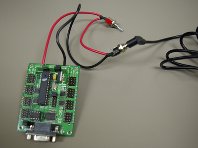
NOTE: there are 2 states on the switch, however both are labeled "On" (there is no "Off" label, just "On" and "On"). The "real" on is shown in the picture.

- Connect the power plug to the wall socket or power bar.
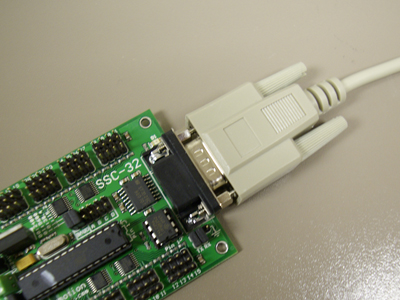
04 :: How to attach the SSC-32 board to the computer
Materials: SSC-32 board, serial cable, computer
- Attach the serial cable to the computer.

- Attach the serial cable to the SSC-32 board.
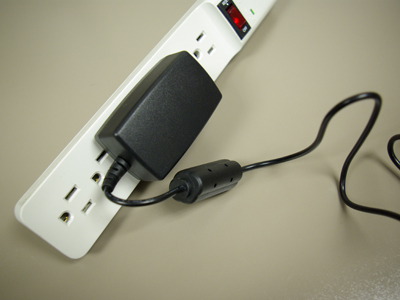
05 :: How to charge the batteries
Materials: Battery charger, battery pack
- Attach the wire end of the battery charger to the battery pack.

- Plug the battery charger into the wall socket or power bar.

Note: Ensure that the battery charger is set to 0.6V, and not 1.2V.
06 :: How to attach a servo to the SSC-32 board
Materials: SSC-32 board, servo
- Connect the black plastic end of the servo wire to a numbered set of pegs on the board, with the black wire (the ground) towards the outside of the board (towards the grounding icon).

- Ensure that you push it down until it snaps into place.

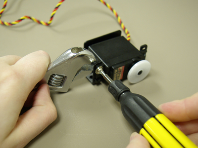
07 :: How to attach a servo to a bracket (general)
Materials: bracket, servo, horn, small black screws (with washers & nuts), silver screws (with washers & nuts)
Tools: screwdriver, wrench
- Fit the servo into the bracket and attach with silver or black screws, depending on hole sizes. Rotate it to the appropriate place so that it is free to move to the maximum and minimum desired positions.

08 :: How to attach a servo to the basic bracket (ASB-04)
Materials: ASB-04 bracket, servo, horn, small black screws (with washers & nuts), silver screws (with washers & nuts)
Tools: screwdriver, wrench
- Rest the servo in the bracket, with the horn facing outwards.
- Use the silver screws to attach the four corners of the servo to the bracket.

09 :: How to attach a servo to the hinge bracket (ASB-03)
Materials: ASB-03 bracket, servo, horn, small black screws (with washers & nuts), silver screws (with washers & nuts)
Tools: screwdriver, wrench
- Unscrew the default horn from the servo. Remove it.


- Fasten the horn to the bracket. Ensure that screws and nuts will not get in the way of servo motion. Two small black screws and nuts will typically suffice.

- Attach the horn to the servo, then place and tighten the servo screw to secure the horn in place.


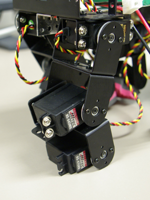
10 :: How to build a basic leg
Materials: ASB-03 bracket, ASB-04 bracket, servo, horn, small black screws (with washers & nuts), silver screws (with washers & nuts)
Tools: screwdriver, wrench
- Attach the servo to an ASB-04 bracket.
- Fasten a circular horn (preferably a metal one) to an ASB-03 bracket.
- Attach the horn to the servo which is held by the ASB-04 bracket.

Note: Ensure that the joints can rotate to the desired minimum and maximum positions in the correct directions for your robot.
- Repeat this process for the other joints.
11 :: How to build a pan & tilt kit
http://www.lynxmotion.com/images/html/build16a.htm
Materials: ASB-03 bracket, ASB-04 bracket, servo, horn, small black screws (with washers & nuts), silver screws (with washers & nuts)
Tools: screwdriver, wrench
- Unscrew the default horn from the first servo. Remove it.
- Attach the horn to an ASB-04 bracket using the small black screws.Two small black screws and nuts will typically suffice.

- Attach the horn on that bracket back onto the servo it originally came from. Set this aside.


- Unscrew the default horn from the second servo. Remove it.
- Attach the horn to an ASB-03 bracket using the small black screws.Two small black screws and nuts will typically suffice.
- Attach the horn with the bracket onto the servo it originally came from.
- Rest the second servo in the ASB-04 bracket, with the horn facing outwards.
- Use the silver screws to attach the 4 corners of the servo to the bracket.

NOTE: You may have to remove the servos from the horns and readjust their rotation before you re-attach them, since servos do have a limited range of rotation, and depending on how they are attached, they may not rotate the amount you want them to in a given direction (or their rotation may be blocked by other brackets).
12 :: How to build a little grip kit
Materials: grip kit, servo
Tools: screwdriver
- Remove the servo horn.
- Attach the grip onto the servo. Make sure it snaps down tightly.

- Ensure that the servo can move appropriately so that the grips open and close fully (or to the desired distances).

13 :: How to start up LynxTerm and check your connection
Materials: SSC-32 board (powered), computer, servo, serial cable
Software: LynxTerm
- Ensure that you have successfully connected the SSC-32 board to the serial port on your computer, and a power source (see How Tos 01-04).
- Launch the LynxTerm application.

- To check if your SSC-32 board is correctly connected to the computer, press the "Reg." button in the bottom left corner of the application. If incorrectly connected, an error message will pop up.

14 :: How to test a servo in LynxTerm
Materials: SSC-32 board (powered), computer, servo, serial cable
Software: LynxTerm
- Ensure that you have at least one servo connected to your SSC-32 board
- Select the desired servo from the dropdown menu in the top-right corner of the application. The numbers representing the servos in the dropdown menu directly correspond to the numbers written next to each servo port directly on the SSC-32 board.

- After selecting a servo, you can test its rotation using the slider beneath the dropdown menu. The values in the slider represent position numbers along the servo's rotation; you can set the minimum and maximum positions using the spinner controls above and below the slider.
NOTE: Each type of servo has a different inherent limit in its rotation, so a servo may or may not actually be able to reach the minimum and maximum positions you set.
15 :: How to start up VSA and the basic set up for the file
Materials: SSC-32 board (powered), computer, servo, serial cable
Software: VSA
- Ensure that you have successfully connected the SSC-32 board to the serial port on your computer, and a power source (see How Tos 01-04).
- Launch the VSA (Virtual Show Automation) application; a blank file will automatically open.
- There are 4 main areas within the VSA interface - the Device View, the Timeline, the Plot View and the Wave View. Though each can be useful at times, the main area that will be used is the Device View. The playback controls for your animation are found on the right-side of the application.

- For the board to be able to communicate properly with VSA, you must set the Baud Rate, which is the "the number of symbol changes (signalling events) made to the transmission medium per second", to 115200. This is accomplished by going to Tools >> Settings, and under the Port Settings tab, double-click the Rate number next to the COM1 port and set its value to 115200.


16 :: How to set a servo's values in VSA & why you need to do this
Materials: SSC-32 board (powered), computer, servo, serial cable
Software: VSA
- Ensure that you have at least one servo connected to your SSC-32 board
- To set a servo's maximum, minimum and default values/positions, you go to Tools >> Settings, and under the Device Settings tab, you will find a chart of all of the possible devices that could be connected to the board (connected, or not). Like in Lynxterm, the numbers of the devices in the list correspond directly to the servo port numbers written on the SSC-32 board.

- To set a value (minimum, maximum, or default) of a servo, double-click the corresponding cell of the desired device. A dialogue will pop up that lists the minimum, maximum and default values for that servo. To change them, simply type in a new value in the input fields. You can test values by using the dial in the dialogue to rotate the servo.

NOTE: it is important to set the values for your devices for two reasons. First, it is helpful to be able to set the maximum and minimum values in cases where you don't want the servo to over-rotate in a direction, whether by you doing it manually, or in an automatically generated animation (ex. movement to an audio file). Second, it is important to set your default values since they represent what your robot will look like at rest - when you reset all of the devices, they will go to this position. For example, for our robotic pony, our default positions had the pony standing straight-up on all fours, with his head and tail at a neutral position, and his jaw closed.
17 :: How to add a movement to a servo on your timeline in VSA
Materials: SSC-32 board (powered), computer, servo, serial cable
Software: VSA
- Ensure that you have at least one servo connected to your SSC-32 board
- In the Device View, click and drag somewhere on the line of the device you would like to add animation to. The length of the bar you create represents how long it will take to complete the animation. You can change the length at anytime by selecting it, and then using the resize handle that appears when you hover over one of its ends with your cursor.


- To change the end position that will be reached in an animation block, you can double-click it to bring up a dialogue. The end position can be altered by entering a new value in the corresponding input field, and values can be tested using the dial within the dialogue.

NOTE: the start value of a servo can not be changed since it is automatically determined by the end position of the previous animation block. If there is no previous animation block (i.e. if it is the first animation block), its start position is set to the default position of the servo (yet another reason why it is important to set the default values before you start your animation).
18 :: How to sync servo movement to an audio file in VSA
Materials: SSC-32 board (powered), computer, servo, serial cable
Software: VSA
- Ensure that you have at least one servo connected to your SSC-32 board
- Load an audio file by going to Tools >> Load Audio File... In the dialogue that pops up, click the "Add" button, then the [...] button that appears towards the top of the dialogue to browse files and select the desired audio file. Click Open to finish selecting the file, then OK to load it.


NOTE: Make sure your file is a .WAV or an .MP3.
- To automatically generate animations based off of the peaks of your audio file, go to Tools: >> WaveMotion Analysis... In the dialogue that pops up, select the device you wish to add the animation to, the minimum and maximum values for the animation, and a Max Error Rate. We found that a value of 15 produced good results, however the lower it is, the more the servo will be sensitive to smaller peaks in the sound (i.e. lower numbers result in more animations at a faster rate). Click OK to generate the animation blocks.


19 :: How to play back your animation in VSA
Materials: SSC-32 board (powered), computer, servo, serial cable
Software: VSA
- To play back your animation a single time press the "Play" button 
- To play back your animation on a loop, press the "Play All Continously" button 
20 :: How to setup up and use the Dremel Tool
Tools: dremel tool kit, drill bit
- Depress the shaft lock button and loosen the collet nut.

- Insert drill bit.

- Tighten the collet nut, while pressing down the shaft lock button.
- To turn the Dremel Tool on, make sure it is plugged in, then use the variable power switch (the numbers represent the different speeds). Refer to the Dremel Tool's instruction manual (found in the Dremel Tool Kit) for details on which speeds are ideal for which materials.

NOTE: Image shows the Dremel tool in the "Off" state.
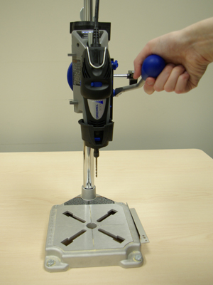
21 :: How to setup and use the Dremel Tool in the Dremel Press
Tools: dremel tool kit, drill bit, dremel press, dremel press wrench
- Unscrew and remove the plastic piece around the drill bit from the Dremel Tool.

- Place the Dremel Tool, drill bit down, into the holder area of the Dremel Press.

- Tighten the large plastic nut underneath the holder area to secure the Dremel Tool in place. Use the Dremel Press Wrench, found on the back of the press, to tighten the nut further.


- To turn the Dremel Tool on, make sure it is plugged in, then use the variable power switch (the numbers represent the different speeds). Refer to the Dremel Tool's instruction manual (found in the Dremel Tool Kit) for details on which speeds are ideal for which materials.
- To use the press, simply pull down the blue lever on its ride side.
22 :: How to hacksaw safely
Materials: piece of metal
Tools: safety goggles, clamp, hacksaw
- Put on your safety goggles

- Loosen the clamp enough to slide in your piece of metal.

- Place your piece of metal inside the clamp.

NOTE: To avoid having grease transfer onto your piece of metal, be sure to cover the clamped area with paper towel.
- Tighten the clamp enough so that the piece of metal is secure and doesn't wobble when pressure is applied.

23 :: How to bend metal on the anvil
Materials: piece of metal
Tools: safety goggles, anvil
- Put on your safety goggles.
- Place your piece of metal over the nose of the anvil and place pressure on either side to bend the metal around it.
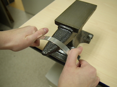
NOTE: If you are going to be drilling holes into the metal, make sure you drill BEFORE you bend.